I was just listening to the latest broadcast of severe thunderstorm and tornado warnings rolling in across WXL-37 for upstate NY:
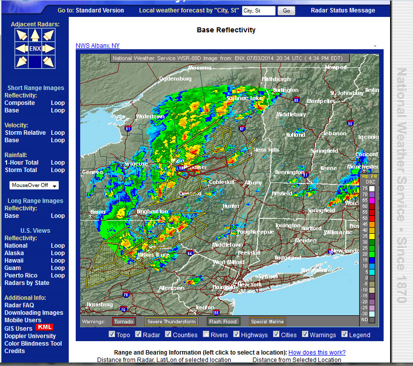
It looks a little bit hairy to the north. There is a lot of rumbling around to the west of us and we are prepared to head for the basement in event of a tornado in this area.
At some point in time, somebody decided that computer-generated voices were exactly right for emergency communications. Never mind some of the quirks that can be encountered. These are mostly pronunciation errors for places like Saugerties, normally spoken as Saw-ger-tees but the NOAA computer voice says S-ouw-jer-tees. That is understood well enough, but frankly, there are other place names that go by so fast that I cannot make sense of what the computer is saying.
Another good example of this is the Coast Guard’s computer voice confusion around the word “November.” In the military (NATO) phonetic alphabet, November is the word used to express the letter N. For some reason, the word itself seems to be a bit of a mystery to the computer, which sometimes renders the word November as “NOVEMBER OSCAR VICTOR ECHO MIKE BRAVO ECHO ROMEO.” For those of us who have been in the military, this makes perfect sense. Why just say “November” when you can say much more, waste time, and confuse the un-aware? This particular computer voice is nick-named “Iron Mike.”
Computer-generated voices can be hit or miss.
Then there is the computer voice from Shannon VOLMET:
Even on HF Single Side Band, that voice is clearly more understandable than the NOAA voices in use today. The issue is, many broadcast stations now use the NOAA computer voice to broadcast weather alerts to their listeners. If I were driving in my car with lots of background noise, I likely would not get most of the information being relayed by the broadcast station via EAS. I suppose gone are the days of a professional broadcaster’s voice clearly imparting information and comforting the listeners during times of calamity. Sigh.