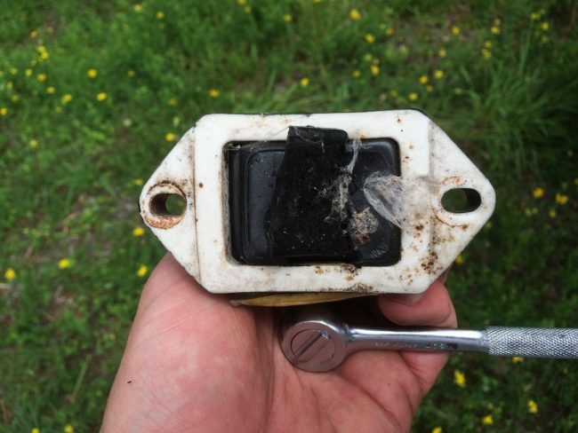
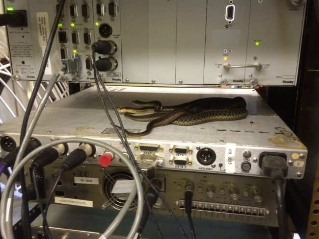
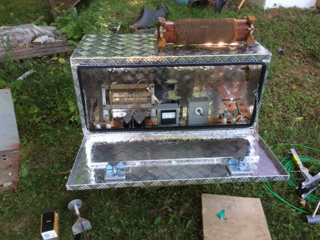
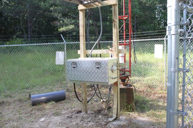
Decommissioning transmitters

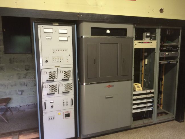
I was at a transmitter site a few days ago scrapping a Continental 814-R1 transmitter. I started thinking (always a dangerous thing) about how many of these units I have decommissioned over the years.  It turns out, quite a few:

Make/ModelYear new*Year removedStationDisposition
GE BT25A19481994WPTRDonated/scrapped
Gates BC5P19602004WWLODonated
Harris MW5A19822000WLNAScrapped
Gates BC1T19612001WLNADonated
Harris FM20H319722001WYJBScrapped
RCA BT1AR19602001WROWDonated
Harris BC1G19722001WDFLAbandoned
Harris FM20H319712005WHUDScrapped
BE FM30A19882005WHUDCannibalized
Harris FM5G19722008WSPKScrapped
Mc Martin BF3.5K19762011WCTWScrapped
RCA BTF-10ES19782011WRKIScrapped
Gates BC1T19642011WINEScrapped
Continental 315F-R119852013WVMTDonated
Collins 813F19752014WKXZScrapped
RCA BTA1AR19652014WCHNScrapped
Collins 813F219782015WKXZScrapped
Collins 830D-1A19682014WKXZScrapped
Harris FM20H319722013WYJBScrapped
Harris BC5HA19732013WROWScrapped
Harris FM10H19712013WMHT-FMScrapped
Harris FM2.5H319732015WEXTScrapped
Mc Martin BF3.5K19722014WSRKScrapped
CCA FM5000G19802015WTBDScrapped
RCA BTF1E19722016WZOZScrapped
QEI 695T3.519962015WBPMScrapped
QEI 695T519962015WBPMScrapped
Harris HT3.519972015WUPE-FMScrapped
Harris Z5CD19972015WXPKCannibalized
Energy Onix SSA100020002015WDHICannibalized
Harris MW119822016WPUTAbandoned
Mc Martin BF1K19822016WSULScrapped
Mc Martin BF3.5K19822016WSULScrapped
Continental 814R119802016WDBYScrapped
Broadcast Electronics FM35A19862017WEBECannibalized
CCA FM-1000D819732018WDLAScrapped
Collins 828E19782018WSYBScrapped
Gates BC-1H19712018WHUCScrapped
Gates BC-1J19542019WBECScrapped
Gates BC250GY19692019WSBSScrapped
Nautel V-7.520092021WSPKCannibalized
Nautel V-1020072023WHUDCannibalized
Harris FM1H319702024WBEC-FMScrapped

*In some cases the “Year New” is a guess based on when the station went on the air.  Before you write me and say “But model XYZ transmitter wasn’t made until 19XX, I did not look at every nameplate and write all the information down as I did this.

Like everything else, there is a process to this.

RCA BTA-10U AM transmitter

First, if the transmitter was made before 1978, the possibility of PCB capacitors and transformers exists. In the case of the GE BT25A, massive amounts of PCBs needed to be disposed of properly. According to current federal laws, ownership of PCBs and PCB-contaminated items cannot be transferred. Thus, the transformer casings were cleaned and taken to Buffalo to be buried in a PCB-certified landfill.   Otherwise, most other transmitters, such as the RCA BTA-10, may have a few PCB capacitors and perhaps the modulation transformer.  Those items can be disposed of by calling an authorized environmental disposal company like Clean Harbors.

The rest of the transmitter is stripped of any useful parts.  Things like vacuum variable capacitors, rectifier stacks, blower motors (if they are in good condition), HV power supply contactors, unique tuning parts, whole control and metering boards, tube sockets, etc.

The remaining carcass is then disassembled and hauled off.  I have a guy that will do this for relatively little money.  He takes the transmitter back to his warehouse cuts it up, sorts the various metals out, and then takes it to the scrap yard.  This includes cutting all the windings off of transformers and power supply chokes, sorting out the brass and copper tuning parts, etc. Thus, most of the transmitter is recycled. Things like vacuum tubes, circuit boards, and other plastic parts are disposed of as e-waste.

The 16 channel bi-directional STL

As a part of our studio build-out in Walton, we had to install a high-capacity STL system between the studio and transmitter site. Basically, there are five radio stations associated with this studio and the satellite dish and receivers are going to be located at the transmitter site.

The audio over IP gear is getting really sophisticated and better yet, more reliable.  For this application, we are using a Cambium networks (Motorola Canopy) PTP-250 radio set and a pair of Wheatstone IP88 blades on either site.  Since there is quite a bit of networked gear at the transmitter site, the IP88s will live on their own VLAN.  The PTP-250s will pass spanning tree protocol, rapid spanning tree protocol, 802.1Q, and other layer two traffic.

The Wheatsone IP88A blades are the heart of the system.  Not only do they pass 16 channels of audio, we can also pass 8 logic closures bi-directionally.  This is key because we are shipping satellite audio and contact closures back from the transmitter site.  The IP88A setup is fairly easy, once the IP address is entered.  The web GUI is used for the rest of the configurations including making the connections between units.

Pair of Wheatstone IP88A AoIP interfaces

The switches are managed units.  The switchports need to be set up via command line to pass VLAN traffic.  There is an appendix in the IP88 manual that outlines how to do this with various managed switches.  This is the most important step for drop-out free audio.  The switchports that connect to the two radios are set up as trunk ports using either VTP or 802.1Q.

Cambium PTP-250 5.8 GHz out door units

The PTP-250 radios were already on hand, new in the box.  They are built really well and look like they should not break in a year or so.  These particular units are connectorized, therefore an external antenna was needed.  There are many such antennas, this system ended up with an RF Engineering & Energy 5150-5850 MHz dual-polarized parabolic dish with RADOMES.  RADOMES are necessary to prevent ice or snow build up in the winter.

RF Engineering & Energy 5150-5850 MHz dual polarized parabolic dish with LMR400 jumpers

STL link dish installed

1 1/2 inch EMT going from TOC to roof

Since the path is only 3.37 miles (5.43 kilometers), I set them up with a 40 MHz wide channel.  This is a rural, small-town setting.  When I looked at the 5.8 GHz band on a spectrum analyzer, it looks fairly uncongested.  These are MIMO single or dual payload selectable.  I will try them as single payload units since the path is short and the band is uncongested.  This should keep the throughput high.

Studio to transmitter site LAN extension

The PTP-250s use POE injectors in mounted in the rack rooms.  CAT5e shielded cable with the proper connectors properly applied is a must for lighting protection.  The PTP-250 units came with Cambium PTP-LPU lightning protectors.  I also installed Polyphaser AL-L8XM-MA type N surge suppressors on each RF port of each PTP-250.

Engineers hate this

Apparently, this coaxial cable has a hot spot:

7/8 inch air dielectric coax with jacket melting off

The back story:

I received a text this morning that one of our client’s stations “had a lot of static on it, it might be off the air.” Upon arrival, I found the Nautel VS2.5 transmitter with 0 watts of forward power and an output network fault. Reset the transmitter and the forward power and reflected power increased together, triggering another output network fault. I was able to turn the transmitter power down to 100 watts, at which point it stayed on, with 50 watts reflected power.  I also noted the dehydrator running continuously and 0 PSI line pressure.

Crap.

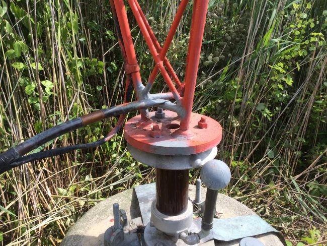
I wandered around the back of the building where the coax goes out to the tower and discovered the dripping plastic from the melted jacket.  I reached up and first checked the cable to see if it was warm (it was not).  Then I shook it and heard what I thought was water sloshing around inside.  This is the original Andrew 7/8 inch cable from when the station signed on in 1972 or so.  Very likely that further up the tower, something has chaffed through the outer jacket and shield, allowing water into the cable.

I drilled a small 5/32-inch hole at the lowest point in the cable before it enters the building.  The result was a steady stream of water, which was aided by some additional pressure from a spare N2 tank.  I let it drain while I ran down to town and got some lunch.  I came back half an hour later, turned the transmitter on, and was satisfied to see 100 watts of forward power with 1 watt reflected.  I ran the transmitter up to full power for a while, then deciding discretion is the better part of valor, and turned it down to half power; 820 watts which net 8 watts reflected power.

Needless to say, the transmission line needs to be replaced as soon as possible.

Came as a stock item

So, I wore out another car and it was time to get a new one. Unexpectedly, the new car came with one of these fancy gizmos:

HD Radio as a stock item

This is not the first HD radio I have owned, the Jeep Cherokee had one that I install myself. This is the first time it came with the car and I didn’t even mention it to the sales guy.

A few observations:

  • Many stations’ HD1 channels don’t sound very good, they are either shrill and tinny, or not synced with their analog counterpart.
  • There still aren’t very many stations transmitting HD Radio; FM stations are either NPR affiliates or belong to a few larger corporate owners.  The AM stations are few and far between.
  • AM HD Radio still has numerous problems in the mobile listening environment.
  • Many of the HD 2/3 don’t sound very good; low audio levels, muffled modulation, low bit rate audio, etc.  The only exception that I have found so far is Vermont Public Radio’s classical format, transmitted on the HD2 of WVPS, Burlington.
  • HD2/3 channels mainly serve as “translator loophole” stations, AKA “Metro Stations”

As far as the new ownership by DTS goes; I will reserve judgment until they do something with it.