I took a brief vacation last week along the coast of North Carolina. It was relaxing and fun to be sure. I was also aware of and slightly curious about the Voice Of America shortwave site, a slight distance inland in Grimesland, NC. Thus, I made arrangements to visit the facility on my way home. Chief Engineer, Macon Dail, was gracious enough to give us the guided tour. The facility is an engineering marvel. The scale and complexity are enormous. The entire facility is scrupulously maintained. Many of the transmitters and other equipment have been upgraded to make them more functional. I tried to take meaningful pictures, but in many cases, they simply do not do justice.
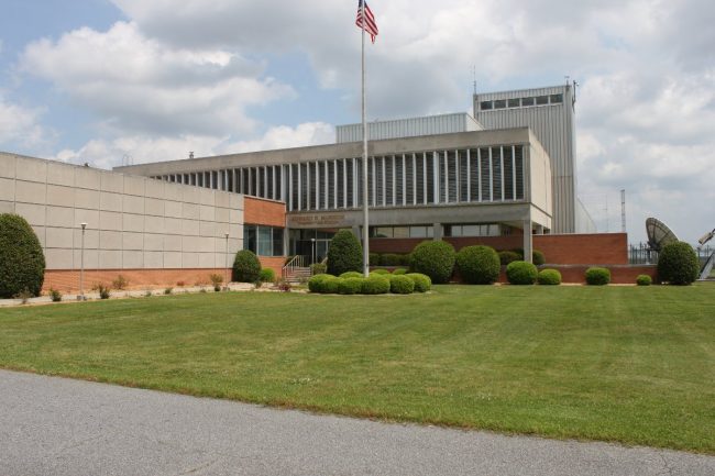
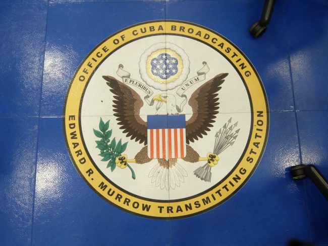
Officially known as the Edward R Murrow Transmitting Station of the International Broadcasting Bureau, VOA Site B was constructed in 1961. Six of the eight shortwave transmitters are original to the construction of the building. The other two (BBC SK55 and AEG S4005) were added in 1986. All of the dipole curtain arrays, rhombics, transmission line, and antenna switching matrices are also original. A few brief statistics about this site:
- Land area is 2,715 acres (1099 hectares).
- Over twenty-six miles (forty-two kilometers) of 300-ohm open transmission line rated at 500 KW.
- Sixteen dipole curtain arrays, average antenna gain 17 dBi.
- Twenty rhombic antennas, antenna gain 15 dBi.
- Two of the dipole curtain arrays can slew azimuth and take off angle.
- Three Continental Electronics 420A 500 KW Doherty modulated transmitters.
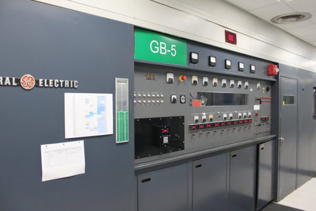
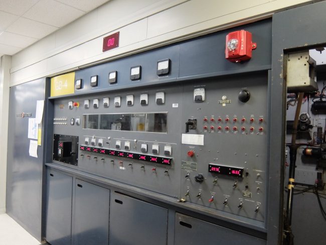
- Three General Electric 4BT250A1 250 KW high-level plate modulated transmitters.
- One Brown Boveri Company (BBC) SK55C3 500 KW PSM transmitter.
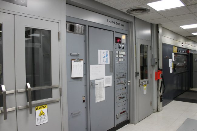
- One AEG Telefunken S4005 500 KW PDM transmitter.
- The antenna switch matrix connects any of the eight transmitters to any of the thirty-six antennas
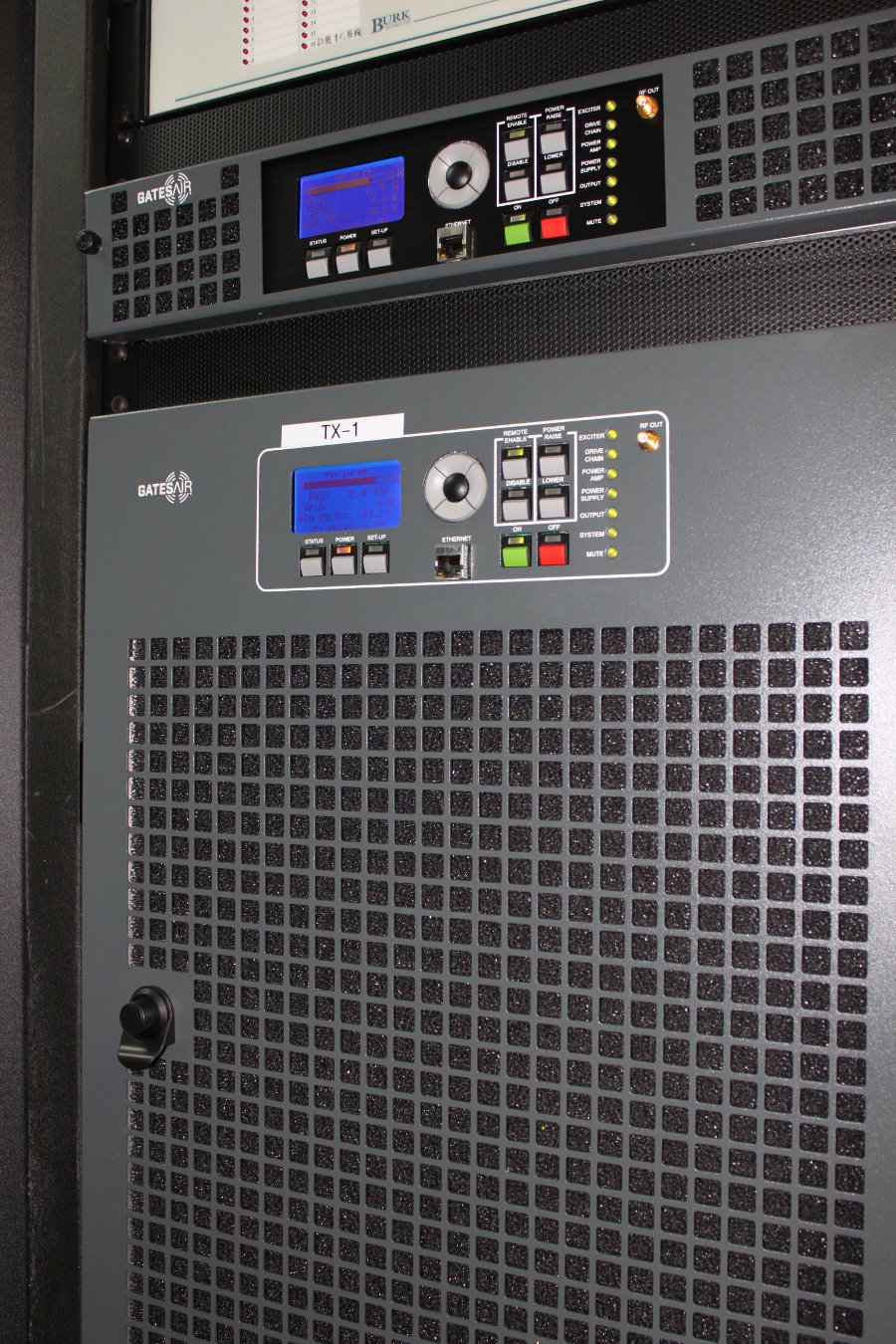
While we were there, both of the newer transmitters were on the air, running at 250 KW. The GE transmitters are used as needed and the Continentals are rarely used due to age, difficulty to tune, change frequencies, and gross power inefficiency.
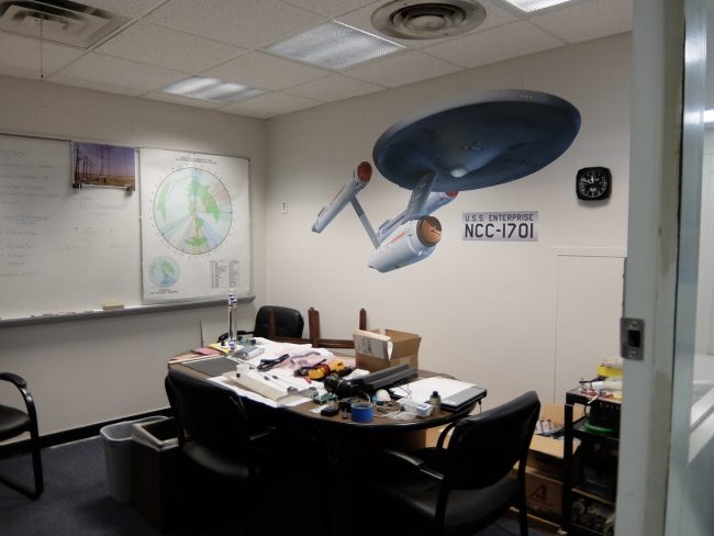
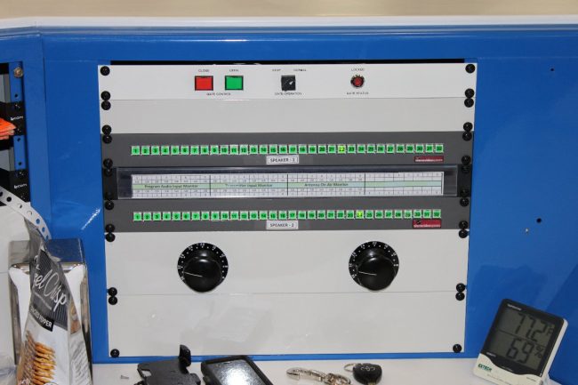
The station staff has, out of necessity, fabricated some very cool upgrades to the transmitters and facility. The first of which is the alarm annunciator, which is based on a Star Trek (Original Series) sound scheme. Once or twice I heard the bridge general alarm go off, followed by a female voice stating the problem: “GB8, OFF AIR.”
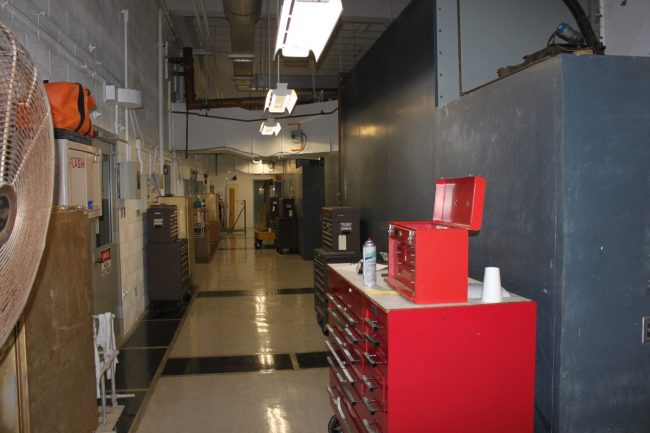
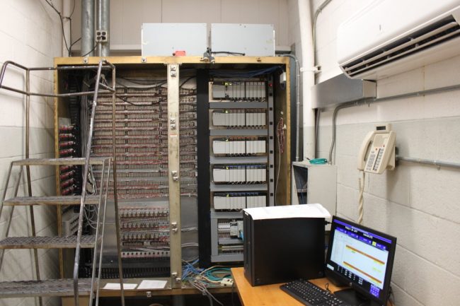
The GE 250 KW transmitters have been retrofitted with a computer-controlled auto-tune system for frequency changes. The antenna switch matrix controller has been replaced by a PLC-based system. As the transmitters are so old, many of the transmitter-specific parts need to be machined or fabricated locally. The rest of the transmitter parts are stocked in a large parts storage room, all of which are meticulously labeled and tracked. The floors are waxed and spotless, there is no dust on the horizontal surfaces, the workshop is clean, tools are put away, grass and weeds are cut, etc. All of these little details did not go unnoticed and indicated great pride by the staff in the facility itself.
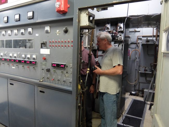
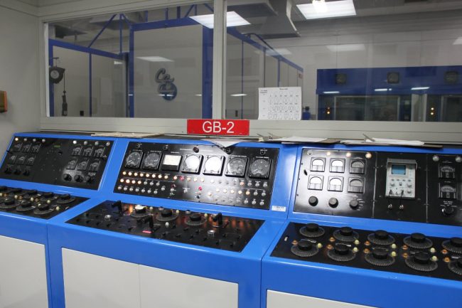
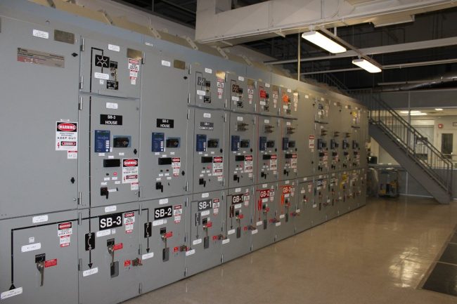
The heart of the facility is the control room which consists of four rows of equipment racks and a central operating position elevated above floor level. Arranged around that are the eight shortwave transmitters in two long transmitter galleries.
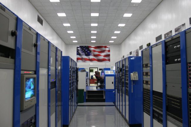
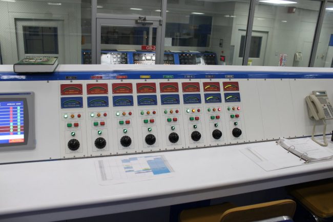
From this point, the operator can view all of the transmitters in the two transmitter galleries.
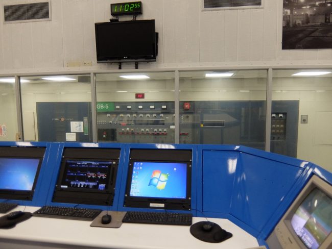
Around the control operator are arranged a series of computer monitors showing various station function status.
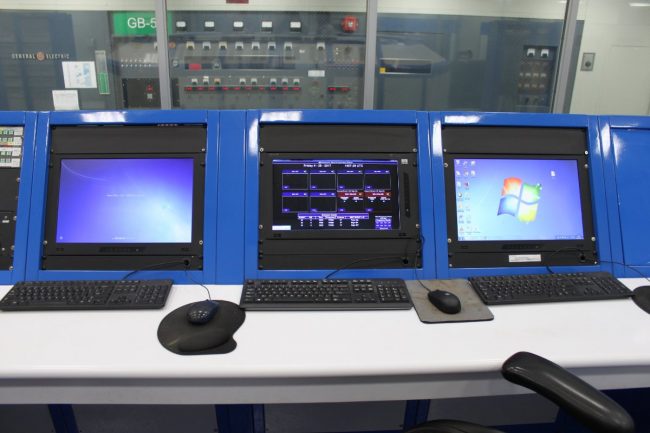
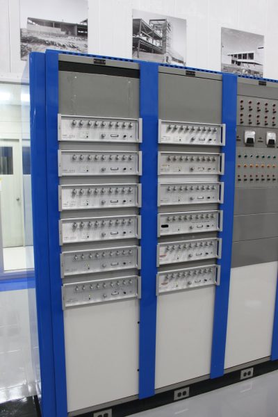
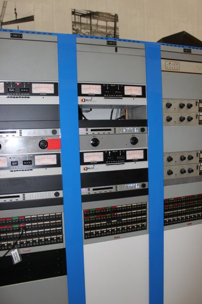
The equipment is installed into the equipment racks by type; one rack contains the frequency generators for each transmitter, the next contains first-stage power amplifiers, the next contains audio processors and modulation monitors, etc.
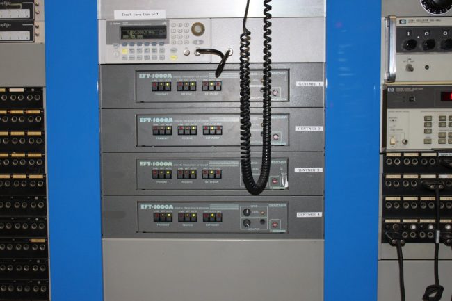
The audio comes from the VOA studios in Washington DC via satellite. There are Comrex Access links as a backup and the Gentner EFT-1000s are used as a backup to the backup. Prior to 1995, an eight-hop microwave system covering the 300-mile (483 KM) distance was used.
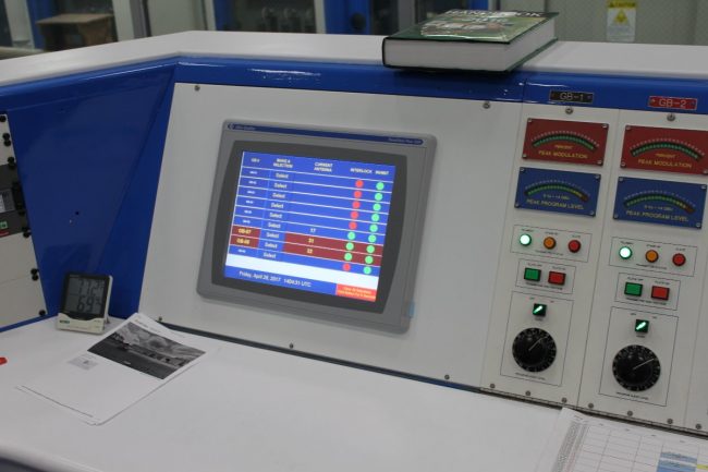
The station staff has created a computer-controlled tuning system for the GE transmitters. Each transmitter can change frequency several times a day, during each frequency change, all of the transmitter stages need to be retuned. When done by hand, this can take several minutes to accomplish. The computer system uses follow pots and microcontrollers to set the tuning elements to specific values. They can be touched up by hand if needed. A frequency change can usually be done in less than one minute.
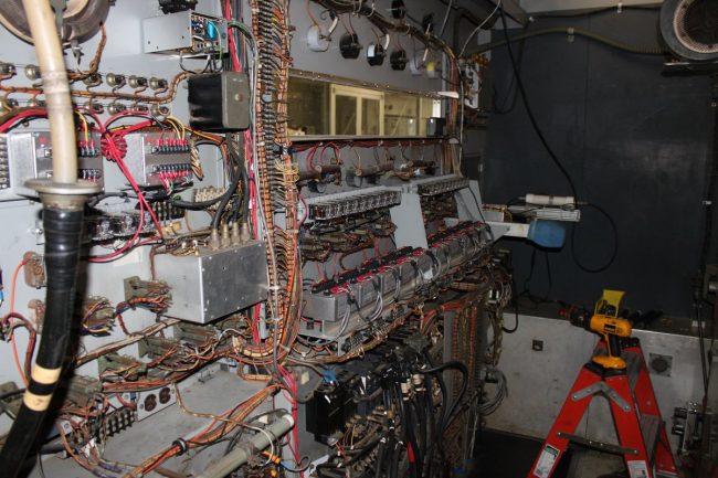
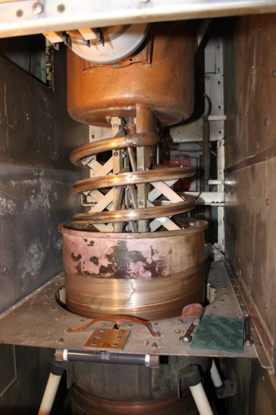
The 2nd IPA and PA input tuning work the same way. The copper sleeve slides up and down over the coil to change resonant frequency. The vapor-cooled tube sits inside the tub at the top, anode facing down. These tuning sections are a mechanical nightmare according to Macon. One of the reasons why VOA site A was closed down was due to the frequent frequency changes at that site causing excessive wear and tear on the old GE transmitters. This particular transmitter was being repaired; the staff was rebuilding a tuning network bypass capacitor assembly
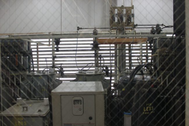
The GE transmitter transformers still contain PCBs. The plate transformers are in the back, basically pole transformers, one for each phase. Primary voltages are 4,180 volts, and secondary rectified voltages are 12 KVDC (PA plate supply) and 15 KVDC (modulator plate supply).
While we were there, the newer transmitters were in operation transmitting Spanish language programming to Cuba on 13,605 KHz and 11,930 KHz. Currently, the Greenville site is broadcasting mostly Spanish language programming with some English, French, and Bambara language programming for Africa.
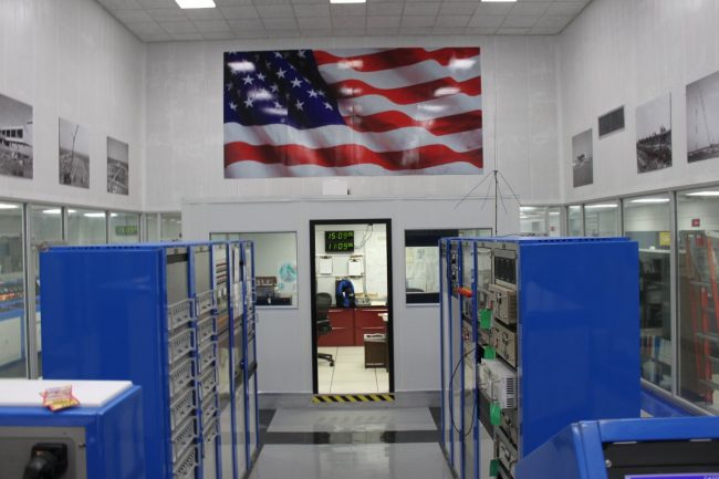
A fact that does not escape the notice of the staff.
The three Continental 420A transmitters (GB-1, GB-2, and GB-3) are essentially a pair of 250 KW amplifiers combined. As these are Doherty power amplifiers, frequency changes are very difficult to effect. These transmitters spend most of their time in backup service.
The antenna matrix building is very impressive. Routing eight 250 or 500 KW transmitters to 36 different antennas takes a bit of doing. Mechanizing that setup is no mean feat. The pictures I took of the antenna matrix building do not show the size and complexity of the system.
For that, we need a satellite photo:
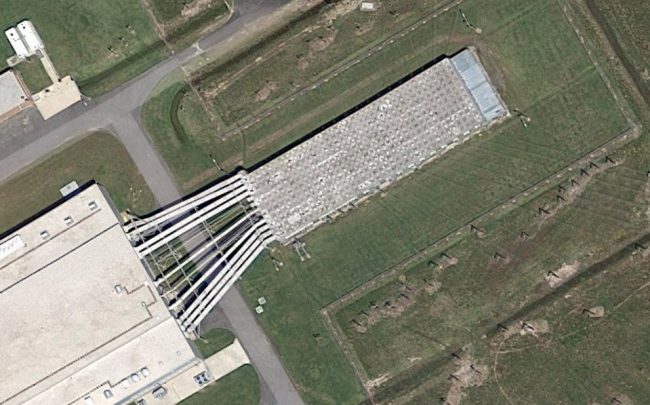
Basically, the transmitter building is in the lower left-hand side of the picture. The transmission line go over to the antenna matrix building (looks like rectangular ductwork), then runs all the way to the back of the building. Each antenna transmission line comes into the building and runs to the other side. Pneumatic arms then couple the transmitter line to the antenna line. This is all controlled by a custom-made PLC and controlled by the operator from the main operating desk.
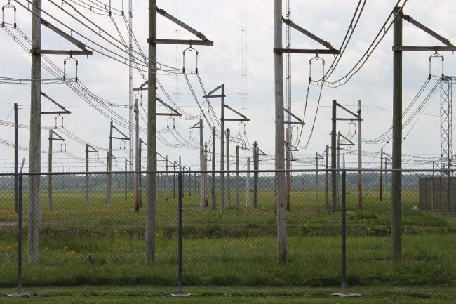
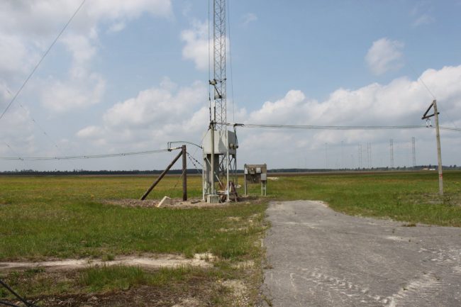
Some of these lines are very long but have low loss due to the air dielectric. The most used antennas are the dipole curtain arrays.
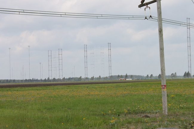
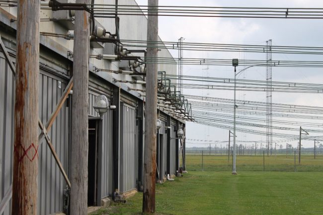
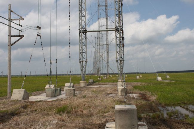
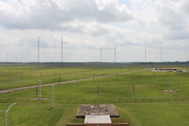
These consist of a series of broadband dipole antennas arranged side by side and stacked three or four high. behind those antennas is a reflector screen. There are two curtain arrays that are slewable. The dipole antenna’s phase relationship to each other can be changed to adjust the takeoff angle and azimuth, thus giving optimum coverage to the targeted area.
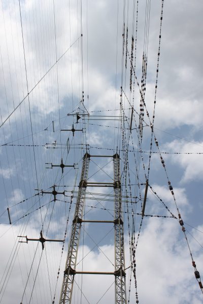
In this picture, the dipole antennas are to the right. Behind them is the reflector screen, and behind that is the antenna feed system. Each antenna feed goes through the reflector screen to the center of the dipole antenna.
Each array requires four towers to support it.
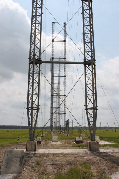
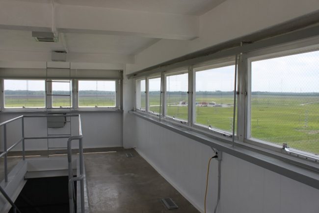
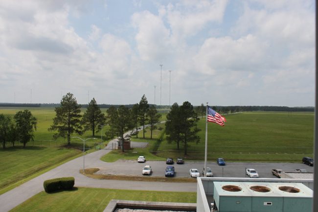
The entire antenna field is viewable from an observation platform on the main building
The entire facility is very impressive. The truth is, I could have spent several more hours there, but I know that people have jobs to do and I felt that I had taken up enough time. We often forget in this country that not everyone in the world has access to the internet. Shortwave broadcasting has a long reach and is not subject to government-controlled firewalls or other forms of electronic censorship. Currently, the Greenville site is broadcasting mostly Spanish language programming with some English language programming for Africa. There are many areas in the world that are in political tension right now, some startlingly close to home. Places like Brazil, Argentina, and Venezuela have been in the news lately. I do not see a time when these long-reach broadcasting services will not be needed. Becoming a welcome source of good information for those affected people is good for brand USA. It would be money well spent to invest in a couple of new Continental 419H (still made in the USA) DRM-capable transmitters for this facility. While the old GE and Continental units are great, the time may come when they are really needed but unavailable due to being down for repair.
Special thanks to Macon Dail for his time, knowledge, and patience.