FCC fines on broadcasters are nothing new. Broadcasters have often tried to cut corners, hiring incompetent staff that cannot be bothered to report tower light outages, or simply not monitoring tower lights at all. Untrained operators who do not know the EAS rules, sloppy public files, unattended main studios, overpower operation, etc. Some AM stations have power changes at sunset and sunrise, most are now automated but who is checking the automation system to make sure the power changes?
The FCC does not have nearly enough field agents to monitor everything. Most rule infractions never get discovered, like the translator operating at double its licensed power. Or the FM station with the antenna at the wrong height on the tower. It never ends. When I first got into this business, I remember one FCC inspector that was going to issue a NOV (Notice of Violation) because the operator signed her name in red ink. RED INK, by god! It seems things have swung far in the other direction.
Fortunately for us, these infractions become public records, so we can all learn from other’s mistakes, right?
Here is the current crop of FCC fines being shuffled through the bureaucracy:
Clarion County Broadcasting Corp. the licensee of radio station WKQW in Oil City, Pennsylvania, apparently willfully and repeatedly violated Section 73.1745(a) of the Commission’s Rules by operating at times beyond the station’s post-sunset authorization. Clarion is liable for a forfeiture in the amount of four thousand dollars ($4,000.00). To determine whether WKQW was operating consistent with its authorization, an agent from the Philadelphia Office installed radio monitoring equipment in Oil City, Pennsylvania to record, on a continuous basis, the relative signal strength of WKQW’s transmission on the frequency 1120 KHz. The equipment was in place from October 28, 2008 to December 12, 2008.The agent reviewed and analyzed the radio transmission data recorded between October 28, 2008 and December 12, 2008, and found several violations. The agent determined that, between October 28, 2008, and October 30, 2008, the station operated after 8:30 p.m. local time, which is the end of the station’s post-sunset authorization during the month of October. The agent also determined from the recorded radio transmission data that, between November 1, 2008 and November 13, 2008 and between November 15, 2008 and November 25, 2008, the station operated past 7:00 p.m. local time, which is the end of the station’s post sunset authorization during the month of November. In response to an inquiry from Commission staff, the owner of Clarion confirmed that the station’s transmitter did not malfunction during the period between October 28, 2008 and December 12, 2008.
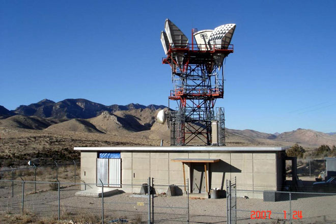
I find it interesting that the FCC has some sort of remote monitoring device that it can install and monitor an AM station’s power levels. I wonder where they installed it. I also have to wonder what it looks like. Is it an outdoor unit, like something one might see attached to a utility pole, or an indoor unit, stashed away in an office somewhere? Very curious, indeed. If I were the station owner, I might ask to see the records that the automated recording device created. That would seem to be a reasonable request.
Caron Broadcasting, Inc. licensee of station WKAT, in North Miami, Florida, apparently willfully and repeatedly violated Sections 73.1745(a) and 73.3526 of the Commission’s Rules by operating at times with power other than those specified in its license and failing to maintain and make available a complete public inspection file. Caron is liable for a forfeiture in the amount of eight thousand dollars ($8,000). We also admonish Caron for the failure of the station’s chief operator to review, sign and date the station logs on a weekly basis as required under Section 73.1870(c)(3) of the Rules.On January, 26, 2009, an agent from the Miami Office monitored WKAT’s transmissions from approximately 5:00 p.m. until 7:00 p.m. The agent made several field strength measurements of the station’s signal and observed no reduction in the transmissions’ field strength after sunset.On January, 27, 2009, an agent from the Miami Office monitored WKAT’s transmissions from approximately 5:25 p.m. until 6:45 p.m. The agent made several field strength measurements of WKAT’s signal and observed no reduction in the transmissions’ field strength after sunset. At 6:43 p.m., the agent made a field strength measurement of the station’s signal one block from the WKAT studio.
On February 5, 2009, at 11:01 a.m., an agent from the Miami Office made a field strength measurement of the station’s signal one block from WKAT’s main studio, which measured approximately the same level as the nighttime measurement that was made there on January 27, again indicating that WKAT was not reducing its power at night. The agent immediately conducted an inspection of WKAT’s main studio with the station’s general manager and designated chief operator. The chief operator stated that the station uses a remote phone monitoring system, which allows the caller to change from day mode (mode “2”) tonight mode (mode “1”). At 11:55 a.m., the chief operator called the transmitter using the remote monitoring system, which indicated that the daytime mode transmitter power was 4,758 watts. At the request of the agent, the chief operator switched the transmitter to nighttime mode, and the system indicated that the power was 316 watts. At 1:45 p.m., with the WKAT transmitter in nighttime mode, the agent made a field strength measurement near the WKAT studio which was much lower than the daytime mode measurement made earlier that day. This measurement confirmed that the station’s transmitter and transmitter remote control system were functioning properly.
Still on February 5, 2009, the agent inspected WKAT’s available daily transmitter logs, which showed that from December 4, 2008 until February 4, 2009, WKAT was not reducing power at night as required by its license. All the log entries made during the daytime and nighttime were in the range of approximately 4,600 to 4,900 watts, and indicated that the transmitter was in mode “2,” the day mode, at all times. The log entries for the early morning hours of February 5, 2009 indicated that WKAT was operating at nighttime power at that time. Neither the station manager nor the chief operator could explain why the power was not being reduced, or why or how the situation was corrected early that morning. The agent also found that none of the station logs were signed by the chief operator or by anyone else. There was apparently no verification of whether or not the station was operating with authorized power, and no initiation of any corrective action for the overpower condition that had been ongoing for several months. The agent also requested to inspect the station’s public inspection file and found that it did not contain the quarterly radio issues/programs lists for the 1st through 4th quarters of 2008. The station manager stated that he did not know where the issues/programs lists were, but that they may be in storage since WKAT moved its studio in August 2008.
They tracked that one down the old-fashioned way, multiple visits at sunset to take field strength meter readings. It seems like no one in this radio group knew anything about FCC requirements and rules. None of this is rocket science, really. These NAL’s are both over a year old. I wonder why it is taking the FCC so long to get through this process.