Mouser Electronics has created a mobile web edition for its online store. This is a handy tool for searching, cross-referencing, and ordering parts. Mouser has a large stock and they ship quickly. Time once was that you could run down to the local electronics store and get just about anything you needed. Even Radio Shack carried a fair amount of small parts, tools, connectors, and so on. Since then, the local electronics shop has closed and Radio Shack’s inventory gets smaller every year. Using a large parts supply company like Mouser or Allied is necessary if any type of troubleshooting and repair is undertaken.
I like the Mouser Mobile site because there is no app to download and install. One simply points the web browser on any mobile device to mouser.com and it will automatically redirect to the mobile site. If that does not work, then m.mouser.com will. The mobile website is easy to browse around, and if needed, a quick call can be made by hitting the little phone icon. Here is more in a video:
Before anyone ever thought to click a mouse and play the latest Ke$ha “song,” or spin Stairway to Heaven for the millionth time, radio was used for a different purpose. Early radio was developed to transmit messages between ship and shore or between continents. Radio apparatus consisted of spark gap transmitters, which were very simple devices only suitable for sending Morse code. Some did experiment with voice modulation methods, but the quality was poor. It was not until Lee Deforest developed the vacuum tube that the state of electronics art was capable of transmitting voice and music.
ATT developed AM (amplitude modulation) for point to point long distance service over high-frequency radio circuits. This is how early intercontinental long-distance phone service was first established. In fact, up until the early 1970s much of the long-distance telephone traffic was routed via high-frequency stations like WOO, WOM, and KMI to Europe and Asia. It was this development that allowed Ham Radio operators to begin transmitting music and other programming to their neighbors and the idea of broadcasting was born.
The Coastal Radio stations that for years transmitted and received messages from ships and sea, transmitted navigation warnings, weather broadcasts, news, and responded to distress calls have all but faded away. The operators of those stations often become nostalgic with the memory of sitting in a small room late at night straining to hear what might be a faint SOS call under all the other chirping CW notes. Successfully “working” a distress call is considered the pinnacle of a shore operator’s career. High-Frequency Continuous Wave (HF CW)(Continuous Wave is the technical description of Morse code modulation) has several distinct advantages for distress work. A small signal can travel long distances and still be well received. The average lifeboat CW transmitter had 5-watt output and often they could be heard across an ocean, 1,000 miles away.
I put together a few lists of these Coastal (ship-to-shore) radio stations. The first is commercial public stations, these were responsible for sending message traffic to and from ships at sea. They often had other purposes like transmitting signals point to point or High Seas Telephone service. High Seas Telephone is just the way it sounds, persons on board a vessel at sea could place a telephone call. It was hugely expensive and was replaced by INMARSAT, which is only moderately expensive.
Call Sign
Location
Owner
Services
Notes
KFS
Palo Alto, CA
Federal Telegraph/ITT
Coastal
Sold to globe wireless, ceased operation 7/12/1999
KPH, KET (point to point)
Pt. Reyes, CA
RCA/MCI
Coastal, point to point
Sold to globe wireless ceased operation 7/1/1997
KLB
Seattle, WA
ShipComm, LLC
Coastal
In service
KMI
Dixon, CA
ATT
Coastal, High seas phone service
Ceased operation 10/8/1999
KSM
Pt. Reyes, CA
MRHS
Coastal
In service
WBL
Buffalo, NY
RCA
Coastal (Great Lakes)
Ceased operation 1984
WNU
Slidell, LA
Coastal
Sold to globe wireless ceased operation 7/12/1999
WLC
Rogers City, MI
United States Steel
Coastal (Great Lakes)
Ceased operation 1997
WCC
Chathem, MA
RCA/MCI
Coastal
Sold to globe wireless ceased operation 1997
WLO
Mobile, AL
ShipComm, LLC
Coastal, (oil rigs)
In service
WOO, WDT (point to point)
Toms River/Ocean Gate, NJ
ATT
Coastal, High Seas and point to point
Ceased operation 10/8/1999
WOM
Pennsuco, FL
ATT
Coastal, high seas phone service
Ceased operation 10/8/1999
WSC
Tuckerton, NJ
RCA/MCI
Coastal
Ceased operation 1978
WSL
Brentwood, Sayville, Southhampton, Amagansett, NY
Federal Telegraph/ITT
Coastal, point to point
Ceased operation 1984
This is by no means an inclusive list as at one time there were hundreds of these stations licensed to the US. There were many inland stations on the Great Lakes and rivers. These are the most common ones that I’ve heard, heard of and or seen personally.
KPH
Most people mark the end of commercial Morse Code as July 13, 1999. There is, however, one station, KSM, which still is open as a public coastal station. That station is a part of the Maritime Radio Historical Society, which operates from the former KPH facilities in Pt. Reyes, California. KPH suspended operations in July, 1997 while other station continued on for the next two years.
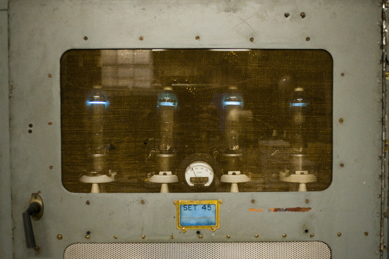
Mercury Vapor Rectifiers from PW-15 transmitter, courtesy of MRHS
Press Wireless was a company used by newspapers to transmit articles and pictures. They developed their own transmitters and operated point to point sites in Hicksville, NY and San Francisco, CA. A few of their transmitters survive today at KPH.
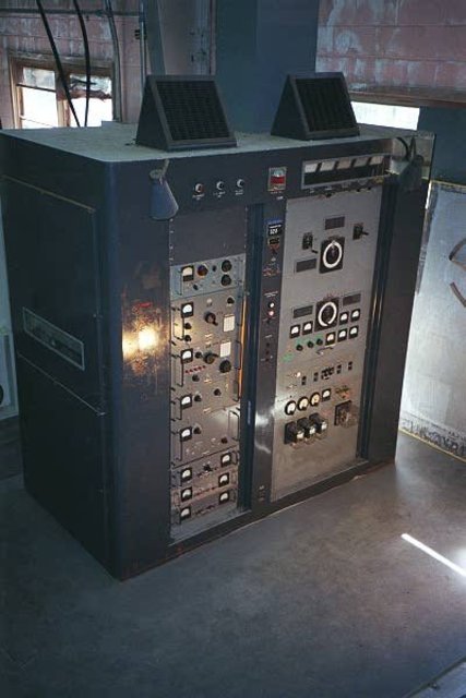
RCA H series HF transmitter, courtesy of MRHS
The 1950s H and K RCA HF transmitters were built to last. The carrier power is 10 KW and can be used for CW, SSB, and RTTY.
KPH is the best preserved Coastal Station, when the facility closed down in 1997, the US Park Service took ownership and left it mostly untouched. In 2004 volunteers and former station employees began to restore the equipment to operation. Eventually, these efforts led to the licensure of KSM, the only operating commercial CW station in the US. KSM uses restored donated equipment from KPH and KFS. Restoration work continues and if I lived closer, I’d volunteer my services. MRHS also operates amateur radio station K6KPH.
WOO
Other facilities survive in parts, the former WOO is home to the Tesla Radio Foundation and Museum. Anyone that knows anything about radio will recognize Tesla as one of the founding fathers, perhaps much more so than Marconi, who often gets more credit than is due. During it’s day, this was a huge facility, connecting North America with Europe, Africa, South America and Asia. Point to Point service included programming relays for the VOA, Long Distance phone service and so on.
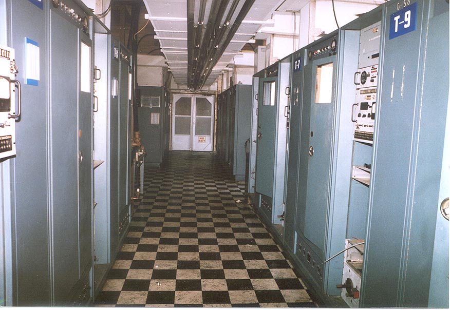
WOO transmitter floor, courtesy of Tesla Foundation
ATT seemed to use the same design for their HF sites, the buildings at KMI, WOO and WOM all look alike, right down to the brown/yellow tile floors.
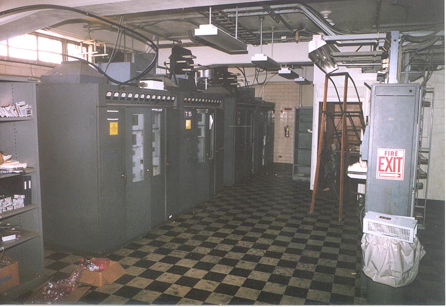
WOO (PW-15 ?) transmitter, courtesy of Tesla Foundation
Again, this facility was restored through the hard work of Radio Amateurs. Unfortunately, unlike KPH, the old CW transmitters where scavenged for parts and none where restorable.
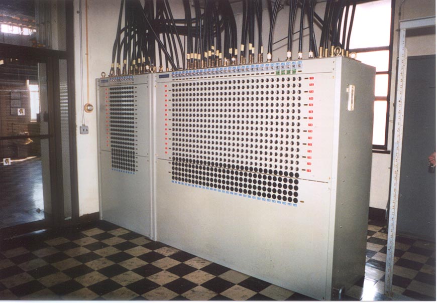
WOO antenna switching matrix
All of the transmitters were routed to this antenna switching matrix. As you can plainly see, there were many, many antennas at this facility. There were also several types, rhombics, verticals, inverted cones, etc. They were (some still are) located in a tidal swamp. From this matrix, with a few exceptions, the transmission lines were routed through BALUNs which then fed open wire transmission lines.
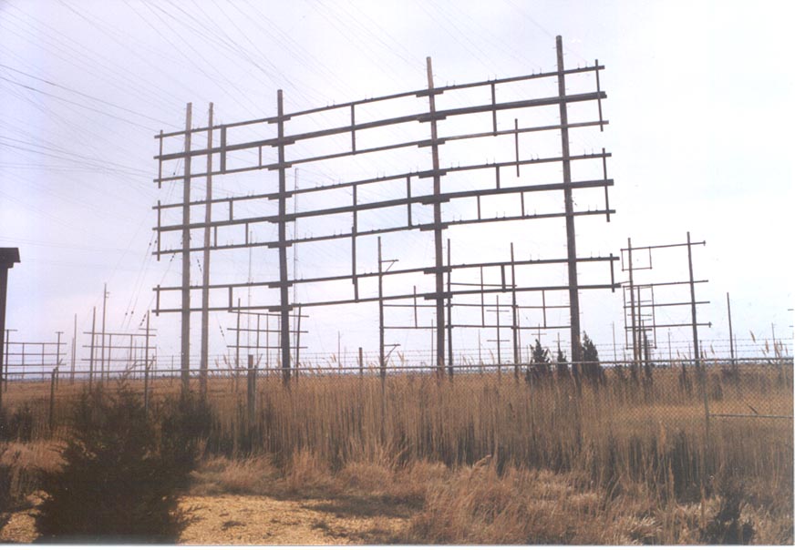
WOO Ocean Gate Radio transmission lines
These lines went to various antenna fields pointed at Europe, South America, Asia and Africa.
WCC
The former WCC receiver site is now home to the Chatham Marconi Maritime Center and has the amateur radio call sign WA1WCC. This is a museum that is open to public. The town of Chatham, with donations from Qualcomm and Verizon, has endeavoured rehabilitate the old receiver site and operations building. They have spent a fair sum of money on replacing plumbing, fixing the driveway and other necessary work to turn the site into a historical attraction and provide a center for Science, Technology, Engineering, and Mathematics (STEM) on Cape Cod.
WCC transmitting antenna, South Chatham, MA courtesy MHRS
We used to go to the public beach right next to this radio tower. It looks like a Milliken tower similar to WICC ‘s towers in Bridgeport. I believe the transmitter site in South Chatham was bulldozed and turned into a wild life refuge.
WLO and KLB are in service with HF voice and SITOR, PACTOR and AMTOR modes but not CW. These stations are operated by ShipCom, LLC.
Coast Guard Maritime Radio
The US Coast Guard operated a network of Coastal Radio stations as well. These where to communicate with Coast Guard vessels and aircraft but also interfaced with civilian shipping. They stretched up and down the east and west coasts, covered Alaska, Hawaii and territories like Puerto Rico and Guam. They ceased CW operations in 1995 and are remotely operated by the two surviving stations, NMC at Pt. Reyes and NMN in Portsmouth, VA.
Call Sign
Location
Services
CW close date
Disposition
NMA
Miami, FL
Limited Coastal, Military
1/4/1995
Remoted to NMN Portsmouth, VA
NMC
Pt. Reyes, CA
Limited Coastal, Military
1/4/1995
In service GMDSS
NMF
Boston, MA
Limited Coastal, Military
1/4/1995
Remoted to NMN, Portsmouth, VA
NMG
New Orleans, LA
Limited Coastal, Military
1/4/1995
Remoted to NMN, Portsmouth, VA
NMO
Honolulu, HI
Limited Coastal, Military, Point to Point
1/4/1995
Remoted to NMC, Pt. Reyes, CA
NMQ
Long Beach, CA
Limited Coastal, Military
1980
Closed
NMN
Portsmouth, VA
Limited Coastal, Military
1/4/1995
In service GMDSS
NMP
Chicago, IL
Limited Coastal, Military
1975
Closed
NMR
San Juan, PR
Limited Coastal, Military
1986
Closed
NOJ
Kodiak, AK
Coastal, Military, Point to point
1/4/1995
In service, GMDSS
NRT
Yokota, JP
Point to point
N/A
Closed 1992
NRV
Barrigada, GU
Coastal, Military, Point to point
1993
Remoted to NMO in 1992, then to NMC in 1995
This is by no means a complete list, there are several more stations that existed but were closed by the mid 1970’s.
GMDSS is the Global Maritime Distress and Safety System, an automated system consisting of satellites and HF radio that replaced the use of manned listening watches on ship and shore. A few years ago, the Coast Guard explored eliminating HFservices all together, however the public outcry was loud and vigorous, thus they didn’t carry through with the plan. Even so, the voice weather and navigation broadcasts are computer generated simulated human voices, which are not a good as the real thing, in this former operator’s humble opinion.
Unlike their civilian counterparts, most of these stations where disposed of without ceremony when they were turned off. Some former Coast Guard Radio Stations were sold off for land, others which were part of existing bases, were dismantled. The only exception to this is the remnant of NMY (New York) on fire island, now administered by the National Parks Service.
There are a fair number of former Coast Guard radio operators with fond memories of working at these places and the satisfaction of a job well done.
If you are interested in history, check out those sites and or pay them a visit if in the neighborhood. You may learn something you didn’t know before.
If one considers paradise an FM35A. Going through another iteration of blown transmitter fuses for WEBE, Bridgeport, CT. Yesterday, I spent the afternoon examining the transmitter and found several interesting things:
Fresh arc tracks on the PA cavity and PA loading capacitor
The shoes and bars in the high-voltage contactor were severely pitted
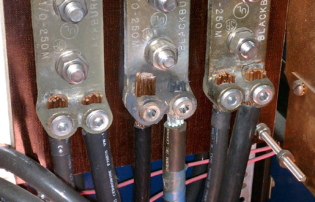
One of the mains phases (middle) in the high voltage supply appears to be heating up, likely due to a loose connection.
Discolored wire on buss bar
I checked and re-tightened all of the mains connections. Apparently, this is an old problem, as the Allen screw was tight. Interestingly, the fuse that was blown was on the red phase, which is different from what it was last time.
I spent the afternoon filing and sanding off the arc track marks in the PA cavity. It is very important to file flat all sharp points that were the result of arcing. Any sharp points will induce corona. I also filed down all of the contacts in a high voltage contactor, which took a fair amount of time. These are soft copper shoes and bars that had so much pitting and carbon I wonder how they didn’t catch on fire. I filed them flat. We were back on the 35A transmitter at full power by 4:30 pm.
If this happens again, I will bring my megger out and check the insulation on the wire between the disconnect switch and the HV power supply.
When I left the site at 5:30, I felt like we did some good work.
This is of interest because of the GE BT-25-A transmitter footage. I do not know the serial number of the WCKY BT-25-A transmitter, but it looks identical to the old WPTR BT-25-A unit which can be seen in this post. As I stated in that missive, I have not heard any transmitter before or since, that sounded as good as this unit. They were really engineering marvels, even in 1999 when this video was shot.
No doubt the MW-50 (no letter) and particularly the DX-50 transmitters are more efficient. In this day and age when many AM stations are just scraping by, overpaying for utilities is not an option. I noticed the Harris MW-50 transmitter with the PDM drawer open. That brings back memories too, those PDM boards were a pain in the rear, as I recall.