Some people work in offices and make lots of money. Others work outside, oblivious to the world going on around them. A fortunate few, myself included, get to work in many different environments, and appreciate them all.
A week or so ago, at the end of the day, I was carrying my tool bag back to the truck and was surprised to see this view:
View looking west from the WRKI transmitter site, Brookfield, CT
The picture really does not do justice. A much wider view is required to get the full effect. It looked like the sky was on fire, something out of a science fiction movie.
Then again, yesterday, I spent the day in a dank, smelly basement tracing out telephone wires. In the end, it all evens out.
An issue I had to deal with recently; was an unstable generator/UPS relationship. When the generator was running under load, it surged repeatedly causing the UPS to drop out and not recharge. Eventually, the UPS ran out of juice and shut down, killing the power to the Sine Systems remote control and telephone system. Of the two, the remote control was the biggest pain to fix, as it lost its timed commands and would not reduce power at sunset for the associated class D AM station.
What went wrong? This is a chart of typical problems with generators operating UPS loads:
Symptom
Potential Problem
Fail to “lock on” to generator power
Improper generator frequency or voltage Poor generator regulation Unrealistic performance requirements
Instability of generator
Voltage regulator sensitivity Control loop compatibility Filter/control interaction Governor or AVR problem
Generator excitation methods can be the culprit in many of these situations. Generators often use one of three types of excitation for their field coils:
Shunt-excited SCR (silicon-controlled rectifier)
Shunt-excited PWM (pulse width modulation)
PGM (permanent magnet generator)
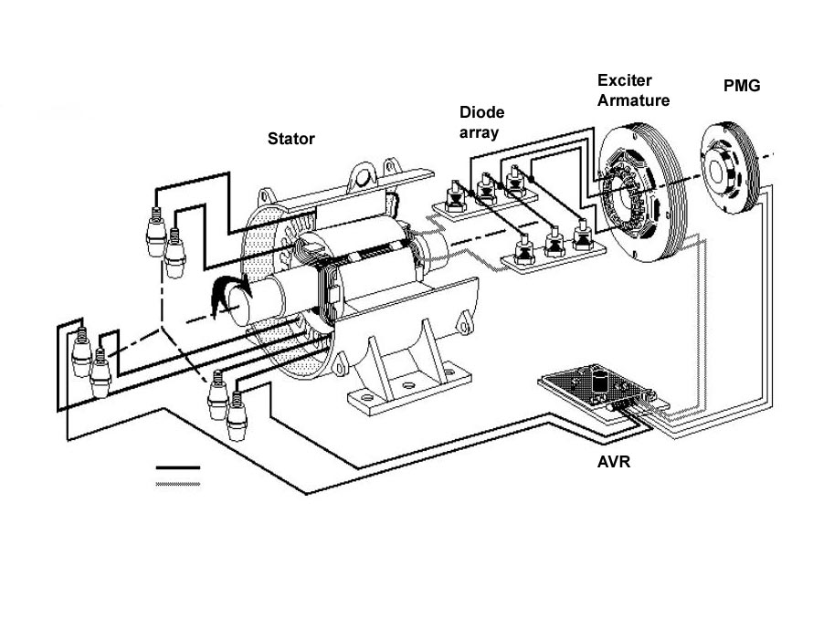
Of the three, the permanent magnet generator is the most stable since the AVR (automatic voltage regulator) is powered by a separate small generator which is unaffected by the load on the main generator output. SCR and PWM both use the generator output windings, which makes them susceptible to load-inducted voltage distortion brought on by non-linear loads. Therefore, in locations where large UPSs are known to be part of the load, PGM-excited generators are the best choice.
PMG generator diagram
Sometimes, the generator is already in use before the UPS is installed. In that case, there are some remedial steps that can be taken. The speed which the voltage regulator reacts to changes in the load is often the culprit in many of these situations. It may seem counterintuitive, however, the faster the AVR reacts, the more fluctuations there will be in the voltage and frequency. A UPS can operate under a wide range of voltages and frequency, provided they do not rapidly change.
Depending on other loads, it may be necessary to dampen the gain on the AVR to slow it’s reactions down. This will work if there are no large intermittent starting loads on the generator such as air conditioning compressors.
Another method would be to delay the UPS transfer to generator power until after all the other loads have been satisfied. This will ensure that the generator voltage and current fluctuations are damped by the existing load.
The generator’s size needs to account for the equipment attached to the UPS and the battery charging load. With a larger UPS, the battery charging load can be significant. Generators that are improperly sized will not be made to work under any circumstances, hence the “unrealistic performance requirements” noted in the chart above.
You can read the entire Cummins Power white paper on generators powering UPS loads here.
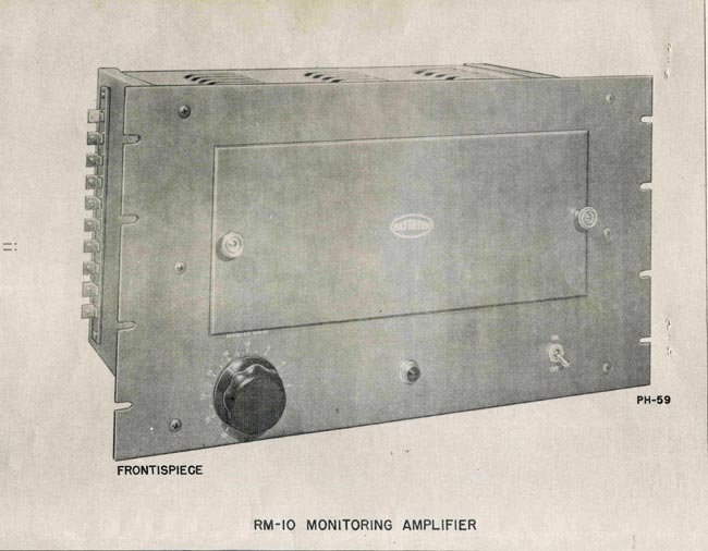
I found this manual from 1946 in the drawer at the WICC transmitter site, which is a sort of time capsule due to its inaccessibility. I figured I would bring it home and scan it, then return it to the file drawer out on the island. Step one is done:
Raytheon RM-10 Monitor Amp
This is a cool little monitor amp, capable of driving line-level or speaker outputs up to about 10 watts or so. It could be used as a front or input stage for a larger audio amp. By the way, 10 watts is a lot more than it seems, if using efficient speakers to convert that power into sound waves. Specs show total harmonic distortion is between 0.6 to 2 percent depending on power and frequency. Lower power output levels net less distortion.
Schematic is pretty simple, a pair of 6L6’s in push-pull for the output. Inverse feedback into the previous stage via the output transformer. Click on image for higher resolution.
I have been watching the LPFM proceedings with some interest. The FCC has not exactly promised to have a filing window by the end of 2012 but indicates that it might try to do that. In comparison to such evolutions in the past, this is moving pretty fast. Those that want an LPFM station need to start planning now. As in previous LPFM windows, the availability is for non-profit organizations only. This does not mean all hope is lost; NPR stations are all non-profits and most of them are very successful.
One of the biggest questions is: How much will it cost? Like all things, it varies greatly. If I were to put an LPFM or internet radio station on the air, there would be certain minimums, such as the use of professional audio equipment, a new antenna, and some type of redundancy.
Generally speaking, radio stations and internet stations both need some type of office/studio space. This can range from large and opulent to a closet. The costs for these would depend on the type and quantity of equipment installed, whether the equipment is new or used, the building, the area, etc. Those facilities also have monthly reoccurring costs such as rent, electricity, telephone service, internet service, etc.
Since internet radio stations and traditional terrestrial over-the-air radio would use the same type of studio equipment, those costs will be similar. Here is a breakdown of the studio equipment:
Nomenclature
Cost new (USD)
Cost used (USD)
Comments
12 Channel professional audio console
$6,000.00
$2,500.00
Used for call-in/on air
Studio Furniture
$5,500.00
$1,000.00
Can also be fabricated locally
Microphones, RE-20 or SM-7B
$250-350
$100-150
Per unit, several required
Monitor Amp
$250.00
$100.00
Can also use consumer version
Monitor speakers
$500.00
$200.00
Can also use consumer version
CD Player
$500.00
$200.00
Professional unit with balanced outs
Computer w/ professional sound card
$1,500.00
$500.00
For automation and sound file storage
Computer, general use
$700.00
$300.00
General information web browsing
Computer, Streaming w/sound card
$900.00
$400.00
Sound card should be good quality
Studio Telephone system
$1,900.00
$300.00
Used for call in/on air
Barix remote box
$240.00 (x2)
N/A
Used for IP remote broadcasts
Comrex Matrix POTS codec
$3,200.00
$700.00
Used for telephone line remote broadcasts
Misc wiring, hardware, ect
$1,000.00
$800.00
Connectors, mic booms, wire, etc
Total
$21,780.00
$7,930.00
Some equipment is not available used such as Barix boxes. Of course, not all of this is required for a radio station, however, most local radio stations would want the capability to do remote broadcasts, take phone callers on the air, have multiple guests in the studio, etc.
For a traditional LPFM station, the transmitting equipment would entail:
Nomenclature
Cost New (USD)
Cost Used (USD)
Comments
300 watt transmitter and exciter
4,400.00
2,000.00
Smaller transmitters with higher gain antennas can also be used
2 Bay ½ wave spaced antenna
$1,900.00
$700.00
125 feet ½ inch coax
$350.00
N/A
100 foot guyed tower and installation
$4,000.00
$3,500.00
Not needed if station is on tall building or leased site
STL; IP radio w/ barix boxes
$850.00
In lieu of standard 950 MHz STL
STL standard 950 MHZ
$6,500.00
$3,500.00
Used in lieu of IP STL
STL antennas, transmission line
$2,500.00
$1,500.00
FM Processor
$10,000.00
$1,200.00
Can also use software such as Breakaway Broadcast
Misc connectors, grounding kits, etc
$1,100.00
N/A
EAS unit
$1,900.00
N/A
Fully operational CAP compliant
Processing software, Breakway broadcast
$200.00
N/A
In lieu of standard FM processor
Total
$12-24K
$8-12K
This is a generic station, most will be somewhat different due to antenna supporting structures, transmitter powers and antenna types. For the best possible signal, a circularly polarized antenna should be used. A two bay, 1/2 wave spaced antenna will give the maximum signal density, while minimizing downward and upward radiation. The upward radiation is simply wasted energy, as no one in space is listening to FM radio. The downward radiation reduction is key if located in congested areas.
For internet radio station, the following would be required:
Nomenclature
Cost New IUSD)
Cost Used (USD)
Comments
Streaming Server
2,100.00
1,100.00
Includes professional sound card
Audio processing software
200.00
N/A
Recommend software such as Breakaway Broadcast
Audio Processing, outboard hardware
650.00
400.00
In lieu of software
Audio Streaming aggregator
1,200 to 2,400
N/A
Annually
While LPFM’s are much more expensive than internet only stations, LPFM’s have the advantage of built in marketing, which is the on air signal. If it is broadcasting on the air, word will get out. On the internet, some other type of marketing will be needed to spread the word. Also, LPFM’s should also be streaming, which would incur the same costs above.
The long and short of it is, to put a technically viable LPFM on the air is not an inexpensive proposition. It is worth the effort, however, because the advantages of an LPFM over an internet only station are great.