It is that time of the year again, at least in the northern hemisphere, for thunderstorms. I am a big proponent of grounding everything, there is simply no such thing as too much grounding. I took a course when I was in the military given by Polyphaser in which grounding for lightning protection and EMP was emphasized. It was very interesting in several respects.

One commonly held belief is that when lightning strikes an object, the ground immediately absorbs all of the charge. That is not true in most cases due to ground resistance. Eventually, the ground will absorb the charge but it can take several seconds to do this, especially with a big strike. Equipment is damaged by current flow, therefore, every effort must be made to keep all of the equipment at the same potential, even if that potential is 10KV. That is where a single-point ground bus comes in. Bonding every piece of equipment to a common ground bus ensures that no one device is at a lower potential while the charge dissipation is occurring.
The second misunderstanding about lightning is that it is DC voltage. That is true, however, a lightning strike has an extremely fast rise time, on the order of 30 microseconds. That makes it behave more like an AC voltage of around 10 KHz. Therefore, ground bus wires need to have a minimum inductance. Solid #2 wire is best, keeping it as straight as possible and using long sweeping turns where needed. All bonds should be exothermically welded (CAD weld).

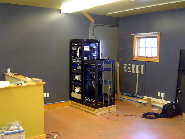
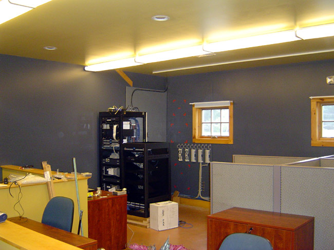
The ground system was installed at WKZY, WHHZ, and WDVH-FM transmitter site in Trenton, Florida. Central Florida is the lightning capital of the US. Prior to doing this work, the Harris FM25K transmitter was knocked off the air at least once a month. Since this was installed in 2005, they have had zero lightning-related damage. The ground rods are 20 feet long, driven down into the water table, spaced 20-30 feet apart.
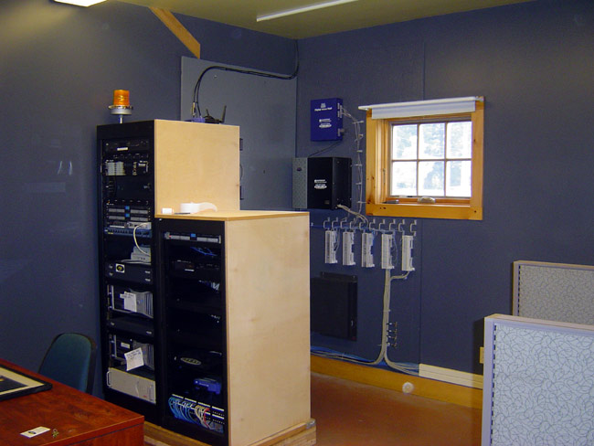
All coax shields and metal conduits that come into the building should be bonded to the ground system where they leave the tower and where they enter the building. At most tower sites, I install a ground ring around the outside of the building with rods every 20 feet or so. From that ring, 5 to 6 radials outward 40 feet with ground rods every twenty feet works well. I also install 5 to 6 radial out from the tower base with the same configuration. The tower and building grounds are bonded together. This is important because when the tower gets hit, the ground will quickly become electrically saturated. If the building and the equipment inside are at a different potential, current will begin to flow toward the lower potential, thus damaging gear.
All Coax, control, and AC cables in and out of sensitive equipment should have ferrite toroids on them. Transmitter manufacturers normally supply these with new solid-state transmitters, as MOSFETs are particularly sensitive to lightning damage.

This is a Potomac Instruments AM-19 directional antenna monitor. It was damaged by a lightning strike two weeks ago on the WBNR tower in Beacon, NY. The case arced to the rack it was mounted in. This was a large strike, as several components in the phasor control circuit were also damaged. The fact that this arced means that somehow the sample lines are not attached to the single-point ground for this site, which needs to be corrected.

Insulated AM towers present special design problems when it comes to lightning protection. Generally speaking, tower arc gaps should be set so there is side by side and there is no arcing on positive modulation peaks. Depending on power levels, this can be anywhere from 1/2 inch to 2 inches. Tower impedance also plays a role in setting arc gaps. The final link between the ATU and the tower should have several turns in it. The idea is to make that path a higher impedance path for the lightning, causing it to dissipate through the arc gaps. Incoming transmission lines from the towers should be bonded to a copper bus bar at the entrance to the building. All of this grounding needs to be tied to the RF ground at the base of the tower.
Arial phone cables can act like large lightning antennas for strokes several miles away. It is very important that the cable shield and the cable termination device are bonded to the building ground buss. I have seen installations where the TELCO tech pounds in a separate ground rod outside and connects the TELCO equipment to that. That defeats the concept of single-point grounds and should be fixed ASAP.
Electrical services entrances also can act like big lightning antennas. Normally, pole-mounted transformers will filter some of this energy out. Internal electrical distribution systems can also add impedance, and thus act as inadvertent filters for lightning. In most mountaintop transmitter sites, however, some type of power line surge protection is needed.

There are two types, series, and parallel. Parallel types are the least expensive and least intensive to install. They are usually found mounted next to or on the service panel and fed with their own breakers. They usually have some type of MOV or similar device that acts as a crowbar across the AC mains, conducting spikes to the ground. Series types go in between the service entrance and the main panel. They include a large inductor designed to force spikes off into shunts. A series-type protector offers more complete protection than a parallel.