Like any good government agency, the FCC in conjunction with FEMA is working on upgrading the acronym-heavy EAS system with CAP, which stands for Common Alert Protocol. CAP includes something that FEMA has been working on something called IPAWS, which stands for Integrated Public Alert Warning System.
The FCC is still in the comment/response process (FCC Docket 04-296) which can get long and drawn out. I would not expect to see any NPRM until late fall 2010 with any changes taking effect in early 2011 or so.
Basically, CAP looks like this:
An EAS to CAP converter monitors a CAP source (think e-mail server) and when a CAP message is received, it converts it to EAS protocol and sends it to an input source of an EAS encoder/decoder. The EAS encoder/decoder then passes that information through and broadcasts it. Of course, the EAS encoder/decoder can still be programmed to pass through specific types of messages for specific areas and ignore all others.
Thus far, several manufacturers have designed CAP converters for use with existing EAS units:
For a TFT-2008 system. Others such as SAGE and Trilithic are integrated into the EAS encoder/decoder units. Basically, the CAP part of the EAS system needs an ethernet port with access to an IP gateway to receive messages from the CAP server located off site. That is the weak link in the system, as far as I am concerned.
It is not like some of our so-called trading partners have been trying to tinker with the inner tubes or anything. It is also not like that same trading partner makes most of the cheap ethernet switches and routers found in many radio stations, hardware that can be easily configured remotely. Configured to redirect certain IP addresses to new, exciting, and exotic locations such as Iran or Pakistan.
Perhaps I am paranoid, or not. It falls back to my time in the military when somebody said “It’s good to be a little paranoid if everyone is out to get you.”
The article goes on about CCD (Colony Collapse Disorder) where entire bee colonies die off for unknown reasons. Some speculate that increased use of pesticides might be to blame (which makes perfect sense to me). Still, others think that cell phone towers are the culprits. Noting:
“Animals, including insects, use cryptochrome for navigation,” Goldsworthy told CNN.
“They use it to sense the direction of the earth’s magnetic field and their ability to do this is compromised by radiation from [cell] phones and their base stations. So basically bees do not find their way back to the hive.”
One study in India involved attaching a cell phone to the side of a bee hive and powering it on for two fifteen-minute periods each day. These researchers found that the honey production in the hive dropped off and the hive queen’s egg-laying was cut in half.
All of that is indeed interesting, but somehow I think that a lot of information is lacking. First of all, any first-year physics student can tell you, the RF field around a cellphone antenna decreases logarithmically as a function of distance. In other words, for each unit of distance away from the antenna, the power density decreases by 10 times. Therefore, placing even a mobile phone directly on a bee hive will likely generate much higher RF fields than would otherwise be encountered, unless there was a bee hive in one of the cell tower antennas.
Secondly, there is no mention of power levels, although the frequency appears to be in the 900 MHz range, if this is the study (.pdf) being referred to in the article.
Finally, the compound referred to, as cryptochrome, is also interesting. Breaking the word down, one finds “Crypto” which means hidden, and “Chrome” which means color. According to the Wikipedia article, which most often can be believed when it comes to such subjects, it is indeed used by some animals to detect magnetic fields. However, RF used by cell phones has long been in use by other technologies such as two-way radio, pagers, cordless phones, baby monitors, TV, early radar, and other high-power emitters. It would be most unusual that RF-induced CCD would just now be showing up.
In short, there is very very thin evidence that cell phones are causing CCD and it is a shame on CNN for propagating such nonsense without doing research.
Here is one of those things that can often be a head-scratcher for the uninitiated:
The FCC database gives antenna height in electrical degrees when what you really want to know is how tall is that tower. Never fear, figuring all this out, requires math. Pretty simple math at that, too. I prefer to do these calculations in metric, it is easier and the final product can be converted to feet if that is desired.
First of all, radio waves travel at the speed of light, known as “c” in many scientific circles. Therefore, a quick lookup shows the speed of light is 299,792,458 meters per second (m/s). That is in a vacuum, in a steel tower, there is a velocity factor, most often calculated as 95%, so we have to reduce the speed of light in a vacuum to the speed of RF in a steel tower.
299,792,458 m/s × .95 = 284,802,835 m/s (speed of a radio wave in a steel tower)
Frequencies for AM radio are often given in KHz, which is 1000 cycles per second. For example, 1,370 KHz × 1000 = 1,370,000 Hz (or c/s)
Therefore:
284,802,835 m/s ÷ 1,370,000 c/s = 207 meters per cycle. Therefore the wavelength is 207 meters.
There are 360 degrees per cycle, therefore:
207 meters ÷ 360° = 0.575 meters per degree
If the height of the tower is 90°, then 90° × 0.575 m/° = 51.57 meters. Add to that the height of the base insulator (if there is one) and the concrete tower base and that is the total tower height.
To convert meters to feet, multiply by 3.2808399.
In the United States, that tower would be 169.78 feet tall.
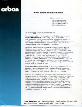
I was digging through some old manuals at the shop today and I found this June 1987 memo from Orban to AM stations titled “AM radio CAN sound almost like FM.”
The main purpose of the memo was to get AM radio stations to implement the NRSC standard for pre-emphasis and high-frequency roll-off to improve the sound of AM broadcasts on ordinary radios.
I am not sure why the receiver manufacturers never designed an IF filter that would be compatible with NRSC, it seems like a fairly simple design. Instead, what we have is “digital” AM radio (IBOC) which does not work well, and creates many more problems with interference than pre-NRSC broadcasting.
If one were to look at the entirety of AM broadcasting history, one would find some striking parallels with what is happening with IBOC today on both AM and FM.
To start, the NAB began petitioning the FCC to allow more AM broadcasting stations, even as it was known that these stations would create interference with existing stations, especially at night. Still, the NAB persisted and the FCC relented and through the fifties, sixties, seventies, and eighties many more class II and III stations were established on what used to be clear channels (classes I and IA).
Once the AM band was chock full of stuff, they began going to work on the FM band with 80-90 drop-ins.
You see, for the NAB, more radio stations means more dues money, and greater lobbying power because of the larger size of the industry. Then came the deregulation of ownership limits. By this time, Big Group Radio was calling the shots and they wanted more. This led to the great consolidation rush of the late 1990s from which the radio industry is still reeling. The consolidation rush led to highly overpriced radio stations being leveraged to the absolute maximum, leading to recent bankruptcies.
Finally, the NAB’s great push toward adopting IBOC digital radio in the early years of the 00s. IBOC was supposed to save the day, greatly improving the quality of both AM and FM and bringing radio into the 21st century. Except that the promised technical advances never materialized. IBOC remains a great expensive boondoggle and I am beginning to think that perhaps we should stop listening to the NAB.
The memo itself is a fascinating thing, which was one could substitute AM with RADIO and come to some of the very same conclusions today regarding analog and IBOC digital radio. For example, this paragraph on AM stereo:
AM stereo was thought to be an answer (to improve AM), but AM stereo was embraced with the false assumption that having ‘stereo’ automatically meant having ‘high fidelity’. While AM stereo did provide somewhat better fidelity, it was not comprehensively engineered to get the best fidelity from AM. It was hoped that the gimmick of having two channels would be enough to save AM.
AM stereo could have been an improvement, had it been properly implemented. Unfortunately, the underlying problem of bad-sounding receivers was never addressed. About which, the same memo notes:
Receiver manufactures did what they could to reduce listener complaints – – they narrowed the bandwidth (thereby reducing audio fidelity) until the complaints about interference stopped. Listeners clearly indicated, through their buying habits, a clear preference for lower fidelity over continuous irritating static, buzzes, whistles, and “monkey chatter’ from adjacent stations. People accepted this situation for a long time – – until the simultaneous advent of improved receiver technology and the FCC’s anti-simulcasting rules created the FM boom of the late 1970’s. (ed note: I remember listening to FM because there were fewer commercials, not better sounding audio)
Then the memo goes on to stress the importance of implementing NRSC standard for AM broadcasting that included the sharp frequency roll-off at 10 kHz, noting that receiver manufacturers would design “fine new receivers” that would take full advantage of the new standard, but only if broadcasters first showed good faith by widely and promptly implementing it.
As I recall, NRSC-1 was adopted as a rule of law by the FCC in 1989, about two years after this memo was written. One could reasonably expect that receiver manufacturers then started producing radios that took advantage of the NRSC pre-emphasis curve with IF filters that did not cut off audio frequencies above 3.5 kHz, but rather rolled them off in a gentle slope until about 7 kHz, more aggressively after that until 10 kHz, where they cut off.
Except they didn’t.
Instead, twenty years later, AM radios universally sound bad, with an audio bandwidth of about 3 kHz or so.
I believe that AM receivers could be made with three IF bandwidths, automatically selected based on signal strength. Within the 5 mv contour, full (10 kHz) audio can be reproduced using a high-frequency roll-off described above. In the 1 – 5 mv contour, a 6 kHz bandwidth and less than 1 mv a 3 kHz bandwidth. The automatic selection could be defeated with a “wide/narrow” IF bandwidth selection switch like the GE super radios have. Of course, if one were listening to stations transmitting AM IBOC, the “narrow” setting would be the best.
Half of me thinks that the ship has already sailed on AM broadcasting. The stations on the air will continue to decline until they are no longer able to broadcast due to expensive repairs or replacement, at which time they will be turned off. The other half thinks that AM radio, as evidenced by the huge public response to WEOK and WALL broadcasting the true oldies channel, can be revived. With the impending inevitable FM IBOC power increases, translator shoe-ins, LPFM, etc; the FM band may become worse than the AM band. At this point, the public will have to decide whether free radio is important to them, or 3G/4G services will become the new method of broadcasting.