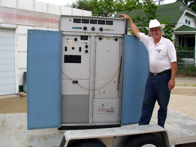
The article goes on about CCD (Colony Collapse Disorder) where entire bee colonies die off for unknown reasons. Some speculate that increased use of pesticides might be to blame (which makes perfect sense to me). Still, others think that cell phone towers are the culprits. Noting:
“Animals, including insects, use cryptochrome for navigation,” Goldsworthy told CNN.
“They use it to sense the direction of the earth’s magnetic field and their ability to do this is compromised by radiation from [cell] phones and their base stations. So basically bees do not find their way back to the hive.”
One study in India involved attaching a cell phone to the side of a bee hive and powering it on for two fifteen-minute periods each day. These researchers found that the honey production in the hive dropped off and the hive queen’s egg-laying was cut in half.
All of that is indeed interesting, but somehow I think that a lot of information is lacking. First of all, any first-year physics student can tell you, the RF field around a cellphone antenna decreases logarithmically as a function of distance. In other words, for each unit of distance away from the antenna, the power density decreases by 10 times. Therefore, placing even a mobile phone directly on a bee hive will likely generate much higher RF fields than would otherwise be encountered, unless there was a bee hive in one of the cell tower antennas.
Secondly, there is no mention of power levels, although the frequency appears to be in the 900 MHz range, if this is the study (.pdf) being referred to in the article.
Finally, the compound referred to, as cryptochrome, is also interesting. Breaking the word down, one finds “Crypto” which means hidden, and “Chrome” which means color. According to the Wikipedia article, which most often can be believed when it comes to such subjects, it is indeed used by some animals to detect magnetic fields. However, RF used by cell phones has long been in use by other technologies such as two-way radio, pagers, cordless phones, baby monitors, TV, early radar, and other high-power emitters. It would be most unusual that RF-induced CCD would just now be showing up.
In short, there is very very thin evidence that cell phones are causing CCD and it is a shame on CNN for propagating such nonsense without doing research.
Here is one of those things that can often be a head-scratcher for the uninitiated:
The FCC database gives antenna height in electrical degrees when what you really want to know is how tall is that tower. Never fear, figuring all this out, requires math. Pretty simple math at that, too. I prefer to do these calculations in metric, it is easier and the final product can be converted to feet if that is desired.
First of all, radio waves travel at the speed of light, known as “c” in many scientific circles. Therefore, a quick lookup shows the speed of light is 299,792,458 meters per second (m/s). That is in a vacuum, in a steel tower, there is a velocity factor, most often calculated as 95%, so we have to reduce the speed of light in a vacuum to the speed of RF in a steel tower.
299,792,458 m/s × .95 = 284,802,835 m/s (speed of a radio wave in a steel tower)
Frequencies for AM radio are often given in KHz, which is 1000 cycles per second. For example, 1,370 KHz × 1000 = 1,370,000 Hz (or c/s)
Therefore:
284,802,835 m/s ÷ 1,370,000 c/s = 207 meters per cycle. Therefore the wavelength is 207 meters.
There are 360 degrees per cycle, therefore:
207 meters ÷ 360° = 0.575 meters per degree
If the height of the tower is 90°, then 90° × 0.575 m/° = 51.57 meters. Add to that the height of the base insulator (if there is one) and the concrete tower base and that is the total tower height.
To convert meters to feet, multiply by 3.2808399.
In the United States, that tower would be 169.78 feet tall.
I was digging through some old manuals at the shop today and I found this June 1987 memo from Orban to AM stations titled “AM radio CAN sound almost like FM.”
The main purpose of the memo was to get AM radio stations to implement the NRSC standard for pre-emphasis and high-frequency roll-off to improve the sound of AM broadcasts on ordinary radios.
I am not sure why the receiver manufacturers never designed an IF filter that would be compatible with NRSC, it seems like a fairly simple design. Instead, what we have is “digital” AM radio (IBOC) which does not work well, and creates many more problems with interference than pre-NRSC broadcasting.
If one were to look at the entirety of AM broadcasting history, one would find some striking parallels with what is happening with IBOC today on both AM and FM.
To start, the NAB began petitioning the FCC to allow more AM broadcasting stations, even as it was known that these stations would create interference with existing stations, especially at night. Still, the NAB persisted and the FCC relented and through the fifties, sixties, seventies, and eighties many more class II and III stations were established on what used to be clear channels (classes I and IA).
Once the AM band was chock full of stuff, they began going to work on the FM band with 80-90 drop-ins.
You see, for the NAB, more radio stations means more dues money, and greater lobbying power because of the larger size of the industry. Then came the deregulation of ownership limits. By this time, Big Group Radio was calling the shots and they wanted more. This led to the great consolidation rush of the late 1990s from which the radio industry is still reeling. The consolidation rush led to highly overpriced radio stations being leveraged to the absolute maximum, leading to recent bankruptcies.
Finally, the NAB’s great push toward adopting IBOC digital radio in the early years of the 00s. IBOC was supposed to save the day, greatly improving the quality of both AM and FM and bringing radio into the 21st century. Except that the promised technical advances never materialized. IBOC remains a great expensive boondoggle and I am beginning to think that perhaps we should stop listening to the NAB.
The memo itself is a fascinating thing, which was one could substitute AM with RADIO and come to some of the very same conclusions today regarding analog and IBOC digital radio. For example, this paragraph on AM stereo:
AM stereo was thought to be an answer (to improve AM), but AM stereo was embraced with the false assumption that having ‘stereo’ automatically meant having ‘high fidelity’. While AM stereo did provide somewhat better fidelity, it was not comprehensively engineered to get the best fidelity from AM. It was hoped that the gimmick of having two channels would be enough to save AM.
AM stereo could have been an improvement, had it been properly implemented. Unfortunately, the underlying problem of bad-sounding receivers was never addressed. About which, the same memo notes:
Receiver manufactures did what they could to reduce listener complaints – – they narrowed the bandwidth (thereby reducing audio fidelity) until the complaints about interference stopped. Listeners clearly indicated, through their buying habits, a clear preference for lower fidelity over continuous irritating static, buzzes, whistles, and “monkey chatter’ from adjacent stations. People accepted this situation for a long time – – until the simultaneous advent of improved receiver technology and the FCC’s anti-simulcasting rules created the FM boom of the late 1970’s. (ed note: I remember listening to FM because there were fewer commercials, not better sounding audio)
Then the memo goes on to stress the importance of implementing NRSC standard for AM broadcasting that included the sharp frequency roll-off at 10 kHz, noting that receiver manufacturers would design “fine new receivers” that would take full advantage of the new standard, but only if broadcasters first showed good faith by widely and promptly implementing it.
As I recall, NRSC-1 was adopted as a rule of law by the FCC in 1989, about two years after this memo was written. One could reasonably expect that receiver manufacturers then started producing radios that took advantage of the NRSC pre-emphasis curve with IF filters that did not cut off audio frequencies above 3.5 kHz, but rather rolled them off in a gentle slope until about 7 kHz, more aggressively after that until 10 kHz, where they cut off.
Except they didn’t.
Instead, twenty years later, AM radios universally sound bad, with an audio bandwidth of about 3 kHz or so.
I believe that AM receivers could be made with three IF bandwidths, automatically selected based on signal strength. Within the 5 mv contour, full (10 kHz) audio can be reproduced using a high-frequency roll-off described above. In the 1 – 5 mv contour, a 6 kHz bandwidth and less than 1 mv a 3 kHz bandwidth. The automatic selection could be defeated with a “wide/narrow” IF bandwidth selection switch like the GE super radios have. Of course, if one were listening to stations transmitting AM IBOC, the “narrow” setting would be the best.
Half of me thinks that the ship has already sailed on AM broadcasting. The stations on the air will continue to decline until they are no longer able to broadcast due to expensive repairs or replacement, at which time they will be turned off. The other half thinks that AM radio, as evidenced by the huge public response to WEOK and WALL broadcasting the true oldies channel, can be revived. With the impending inevitable FM IBOC power increases, translator shoe-ins, LPFM, etc; the FM band may become worse than the AM band. At this point, the public will have to decide whether free radio is important to them, or 3G/4G services will become the new method of broadcasting.
It is that time of the year again, at least in the northern hemisphere, for thunderstorms. I am a big proponent of grounding everything, there is simply no such thing as too much grounding. I took a course when I was in the military given by Polyphaser in which grounding for lightning protection and EMP was emphasized. It was very interesting in several respects.
One commonly held belief is that when lightning strikes an object, the ground immediately absorbs all of the charge. That is not true in most cases due to ground resistance. Eventually, the ground will absorb the charge but it can take several seconds to do this, especially with a big strike. Equipment is damaged by current flow, therefore, every effort must be made to keep all of the equipment at the same potential, even if that potential is 10KV. That is where a single-point ground bus comes in. Bonding every piece of equipment to a common ground bus ensures that no one device is at a lower potential while the charge dissipation is occurring.
The second misunderstanding about lightning is that it is DC voltage. That is true, however, a lightning strike has an extremely fast rise time, on the order of 30 microseconds. That makes it behave more like an AC voltage of around 10 KHz. Therefore, ground bus wires need to have a minimum inductance. Solid #2 wire is best, keeping it as straight as possible and using long sweeping turns where needed. All bonds should be exothermically welded (CAD weld).
The ground system was installed at WKZY, WHHZ, and WDVH-FM transmitter site in Trenton, Florida. Central Florida is the lightning capital of the US. Prior to doing this work, the Harris FM25K transmitter was knocked off the air at least once a month. Since this was installed in 2005, they have had zero lightning-related damage. The ground rods are 20 feet long, driven down into the water table, spaced 20-30 feet apart.
All coax shields and metal conduits that come into the building should be bonded to the ground system where they leave the tower and where they enter the building. At most tower sites, I install a ground ring around the outside of the building with rods every 20 feet or so. From that ring, 5 to 6 radials outward 40 feet with ground rods every twenty feet works well. I also install 5 to 6 radial out from the tower base with the same configuration. The tower and building grounds are bonded together. This is important because when the tower gets hit, the ground will quickly become electrically saturated. If the building and the equipment inside are at a different potential, current will begin to flow toward the lower potential, thus damaging gear.
All Coax, control, and AC cables in and out of sensitive equipment should have ferrite toroids on them. Transmitter manufacturers normally supply these with new solid-state transmitters, as MOSFETs are particularly sensitive to lightning damage.
This is a Potomac Instruments AM-19 directional antenna monitor. It was damaged by a lightning strike two weeks ago on the WBNR tower in Beacon, NY. The case arced to the rack it was mounted in. This was a large strike, as several components in the phasor control circuit were also damaged. The fact that this arced means that somehow the sample lines are not attached to the single-point ground for this site, which needs to be corrected.
Insulated AM towers present special design problems when it comes to lightning protection. Generally speaking, tower arc gaps should be set so there is side by side and there is no arcing on positive modulation peaks. Depending on power levels, this can be anywhere from 1/2 inch to 2 inches. Tower impedance also plays a role in setting arc gaps. The final link between the ATU and the tower should have several turns in it. The idea is to make that path a higher impedance path for the lightning, causing it to dissipate through the arc gaps. Incoming transmission lines from the towers should be bonded to a copper bus bar at the entrance to the building. All of this grounding needs to be tied to the RF ground at the base of the tower.
Arial phone cables can act like large lightning antennas for strokes several miles away. It is very important that the cable shield and the cable termination device are bonded to the building ground buss. I have seen installations where the TELCO tech pounds in a separate ground rod outside and connects the TELCO equipment to that. That defeats the concept of single-point grounds and should be fixed ASAP.
Electrical services entrances also can act like big lightning antennas. Normally, pole-mounted transformers will filter some of this energy out. Internal electrical distribution systems can also add impedance, and thus act as inadvertent filters for lightning. In most mountaintop transmitter sites, however, some type of power line surge protection is needed.
Inside view of LEA surge suppressor
There are two types, series, and parallel. Parallel types are the least expensive and least intensive to install. They are usually found mounted next to or on the service panel and fed with their own breakers. They usually have some type of MOV or similar device that acts as a crowbar across the AC mains, conducting spikes to the ground. Series types go in between the service entrance and the main panel. They include a large inductor designed to force spikes off into shunts. A series-type protector offers more complete protection than a parallel.