The case of the blown fuse, or rather the blown up fuse:
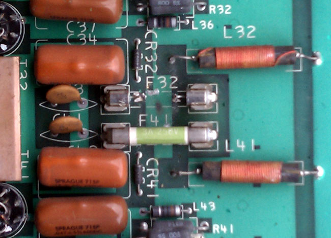
Blown 10 amp fuse on Harris SX5 PA board
F32 is blown into small bits and had to be vacuumed out of the bottom of the transmitter. The reason why is the pair of MOSFETs connected to that circuit were shorted. Of course, the reason for the shorting of MOSFETs needed to be investigated. What I found was on the underside of the PA board where the brass stand-off attacked the toroid combiner board, the nuts attaching the stand-off to the combiner board were loose and there was a big arc mark.
I tightened everything up and replaced the MOSFETS, marking them with a pen in case they short again, in which case the drive section needs to be closely examined.
It was a hot day, it was a cold day. The tube transmitter was running, the solid-state (HD-1) transmitter was off the air. The books show that the company has deep pockets, but the accountant has short arms. And so it goes. In a sordid, yet familiar tale of leaping three-quarters of the way across a river, the builders of this transmitter site seemed to think of everything except the cooling requirements for a 35 KW FM transmitter.
Instead of installing real commercial AC units, someone decided that 34,000 BTU window units were the way to go. At one time, there were eight of those units, all single phase 240 volts sucking down gobs of power and freezing up when the outside temperature dropped below 40°F. This was always a problem but became more so when we took over the maintenance of this site. When there was a full-time engineer, his time, apparently, could be wasted running back and forth turning the window units on or off in the winter as required. Now that a contract company is doing the work, it becomes cost prohibitive to require such things.
Therefore, the time had come to make a change. To that end, six of the 34,000 BTU window units were removed from the building. Two of the existing holes in the wall were used to create an emergency cooling system, consisting of a 4,292 CFM fan and a couple of shutters. Two other holes were used for the new air conditioners and two holes were blocked up. The remaining two window units were left in place in the combiner room, which is a separate cooling zone.
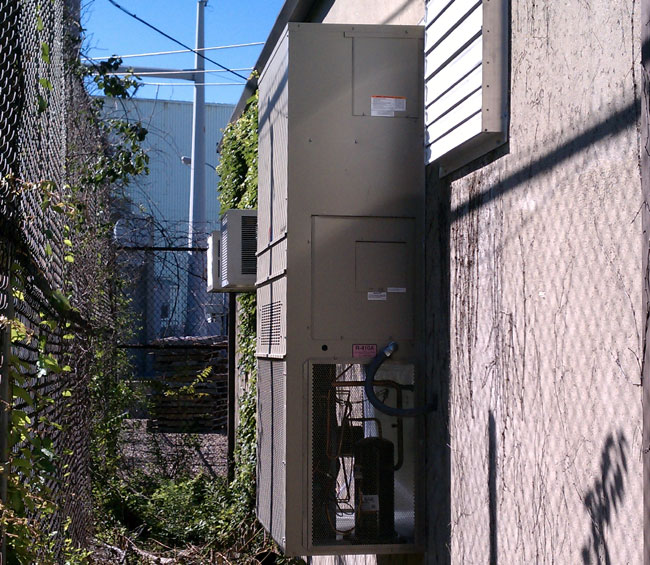
Bard 5-ton wall mount AC unit and cooling fan shutter
The new ACs are five-ton wall-mount Bard units. These are three phase and should be more than enough to keep the transmitters cool. Here is how I arrived at that conclusion:
The entire building load when the main transmitter is running at full power, without the transmitter room air conditioning, is 60 KW.
All of the building loads except the transmitters go through a single-phase panel.
The load on the single phase panel is 10 KW, thus the transmitter load is 50 KW (this 10 KW is mostly the single phase AC units in the combiner room)
The TPO is 32 KW, therefore the transmitter is generating 18 KW of waste heat.
One watt-hour = 3.412 BTU of energy, thus
18,000-watt-hours equals 61,416 BTUs
One ton = 12,000 BTU, thus
61,416 BTU ÷ 12,000 BTU = 5.118 tons
That will take care of the main transmitter waste heat. The HD transmitter generates another 4,000 watts of waste heat or 1.37 tons. The combiner is in another room and doesn’t factor into the calculation. The rest of the equipment is inconsequential, adding up to less than 100 watts.
The solar gain is more difficult to calculate, as it is based on the building structure, the type of construction, and the heat gain (loss) through the walls and doors. This building is concrete block, insulated, and has no windows. It is unshaded, however, it is painted a light color. All in all, the solar gain should be less than two tons on a hot day. Therefore the total AC load should be 8.25 tons or less.
Bard 5 ton wall mount AC unit
All that is left now was to install the things. Just pull up the truck and use a crane to lift them in place, except, no; that plan won’t work. This is the transmitter site at the power plant and the 138 KV lines overhead precluded any lifting with a crane. We instead had to build ramps and move things around on large-hand trucks. One unit is installed on the rear of the building, the other on the front. It required several days to make the ramps and four people to muscle the things into place.
The bottom air intake holes needed to be cut out for the new units. Cutting into the concrete block while the BE FM 35A was running proved to be another challenge. We used several sheets of plastic, shop vacs, and extra air filters on the transmitters to keep the concrete dust out of the PA cavities and motor bearings.
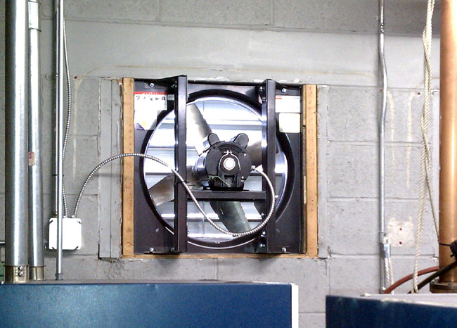
Plan B cooling consists of a 4,292 CFM Venturi fan mounted on the rear wall of the building. The fan is controlled by a ceiling-mounted thermostat set to 95 degrees. If the AC’s fail, the ceiling temperature will rise and the fan will turn on.
Transmitter site emergency cooling fan
The room volume is about 3600 cubic feet, therefore this fan will change the room air about once every 60 seconds or so. It is not the best plan to move humid, potentially dirty outside air through a building, but it it keeps the station on the air while the main AC units are being repaired, then so be it.
The entire system went on line last week and is working well.
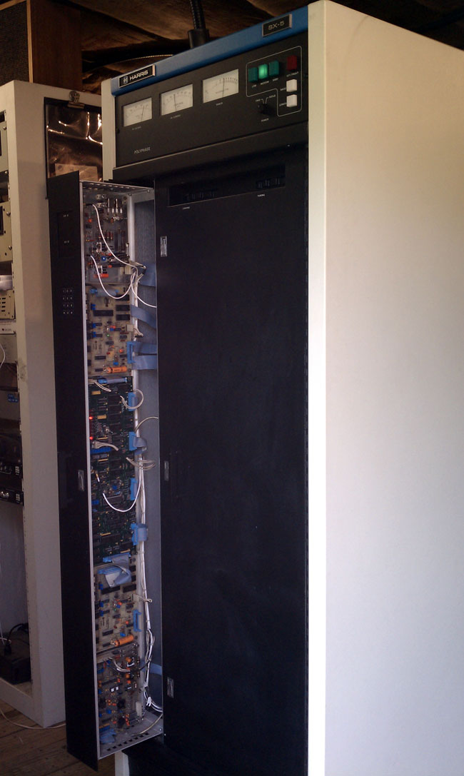
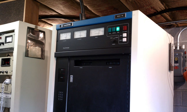
I give you joy, the unmitigated joy, and sheer pleasure of the Harris SX 5 AM transmitter. This particular unit dates from 1984 and is installed at WUPE in Pittsfield, MA. It has a few issues of late.
Harris SX 5 medium frequency AM transmitter
The first of which is the unbalanced or out-of-ratio condition of the PA current and voltage. When changing power levels, the PA current, and voltage are supposed to track together. When they do not, it is an almost sure sign that one or several of the MOSFETS in the PA are shorted. Shorted IRF-350 MOSFETS are indicated by blown fuses on the PA boards and should be replaced in pairs. The reason for the damaged devices also needs to be investigated. It is entirely possible that the site receives a lot of lightning, which can cause this damage. It could also be heat related, as the site is not currently air-conditioned. The other possibility is under drive conditions.
The MOSFETS turn on and off at a rate of 1/(carrier frequency (hertz)) times per second. If they are under-driven, they will go full-on and short-circuit. The minimum drive is 27.5 volts peak to peak, anything less than that is marginal and can lead to the destruction of the PA devices. Underdrive indicates an issue with the oscillator, which has its own set of peculiar failure modes.
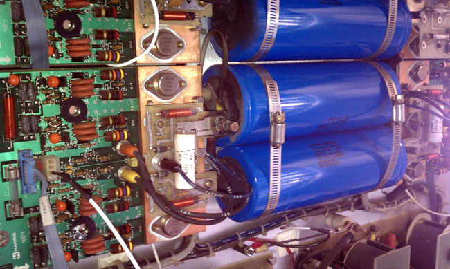
Since this is an older unit, all of the large electrolytic capacitors are also suspect and need to be replaced. There are three power supply capacitors at the bottom of the transmitter, two 76,000 μF 40 VDC for low voltage and one 7500 μF, 350 VDC for high voltage. The modulator section also has six 5100 μF 350 VDC capacitors, collectively known as “dynamite sticks” due to their explosive potential if installed incorrectly.
Harris SX 5 modulator section
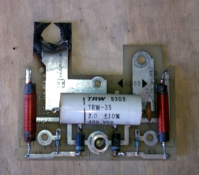
While replacing the dynamite sticks, I noticed this PDM pickup board has a whole burned through it. This is a part of the modulator section and if it burned completely open, would likely cause all sorts of problems with this transmitter, likely spurs all around the dial, distorted modulation or perhaps overload and fail altogether.
Harris SX 5 transmitter damaged PDM pull-up board
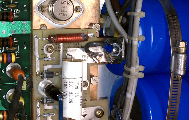
I managed to fix it with a jumper between what is left of the circuit board trace and the capacitor mounting bracket. I soldered the jumper to the board face and soldered the wire lug. After scraping all the oxidized metal off of the capacitor mounting bracket, I attached with a screw. The board itself needs to be replaced, if it is still available from Harris, which it may not be as support for this transmitter was dropped in 2008.
Harris SX5 PDM pull up board temporarily repaired with wire jumper
The worst, and I mean worst possible situation with these transmitters is some type of control malfunction. The control boards and oscillator are in that large vertical pull-out drawer. God protect and preserve the digital control and S and M boards, as they are a major headache to troubleshoot. They have 7300 TLL (5-volt logic) that controls all functions and only a little problem will cause the entire transmitter to shut down.
Other SX series transmitter tips can be found here.
I didn’t get to replacing the blown devices because of a looming electrical storm, which precludes working inside of transmitters. I’ll get back there next week and finish the job.
Update: I finished the repair job today 8/24. There were 16 blown MOSFETS on the PA boards. I checked the drive levels on the input side of the RF torrid load resistors and it is with normal range. I also found this snake in the bottom of the transmitter across the HV shorting bar.
Small grey rat snake, electrocuted by Harris SX 5 transmitter
Could have been chasing diner. Overall, the site needs help. The air conditioner is coming next week.
Harris SX 5 transmitter fully operational
After repairs, the transmitter is back at full power and modulating +125% again.
I thought it would be interesting to do a comparison between the two types of transmitters, both AM and FM. I have been doing this thing for 25 years and have quite a bit of experience working on all types of transmitters. Some of the broadcast transmitters I have personally worked on over the years include:
CSI/CCA, Visual, Energy Onix, Bauer, McMartin, QEI, some Italian something or other, etc. Various makes and models.
I think I have a fair amount of transmitter experience under my belt. What I have found is that certain brands of transmitters are better than others, regardless of whether they are tube or solid-state. There are several differences in each type, obviously. As to some blanket statement about which is better, solid state or tube, I don’t have one. My statement would be “It depends.”
Tube transmitters are more rugged and will take more abuse than a solid-state unit. Things like heat, lightning, EMP, and mismatched antenna won’t phase a well-designed, well-manufactured tube transmitter. On the other hand, they are less efficient AC to RF, have higher B+ voltages, have hard failure modes, and are more difficult to linearize, if that is required for some reason.
Solid state transmitters are more broad-banded, easier to change frequency, they have soft failure mode due to redundant amplifiers and power supplies. The voltages are lower, thus they are safer to work on.
Here is a complete list of advantages and disadvantages of each type:
Attribute
Tube
Solid State
Comment
Ruggedness
Very rugged, able to take heat, EMP, lightning, mistuned antenna, poor operating environment, etc
Not heat tolerant, lightning and EMP can damage MOSFETS, switching power supplies sensitive to AC mains issues
Advantage: Tube
Electrical Efficiency
Less efficient
More efficient
Advantage: Solid State, however efficiency gain can be wiped out due to larger air conditioning requirement
Failure mode
Hard, most often
Soft, most often
Advantage: Solid State, failure of a single module or power supply generally will not take unit off the air
Frequency agility
Difficult
Easy
Advantage: FM Solid state transmitters can easily be moved. AM transmitters still require extensive retuning.
Re-occurring cost
More
Less
Advantage: Solid State, as tube changes are required every two to three years
Maintenance
Same
Same
Advantage: neither
Servicing
Requires skilled engineers to service and trouble shoot
Modules and power supplies are often hot swappable and returned to manufacture for repair
Advantage: Solid State, however either type requires occasional measurements with specialized test equipment
Servicing safety
High voltages, contact will be fatal
Lower voltages, but can still be fatal
Advantage: Solid State
Redundancy
Low
High
Advantage: Dependant on TPO, Higher powered solid-state transmitters are much more expensive than there tube type counterparts
Cost
Less
More
Advantage: Dependant on TPO, Higher powered solid state transmitters are much more expensive than there tube type counterparts
Availability
Good used market, some new FM transmitters still being built
Good new and used
Advantage: Tube
Reliability
Dependent on brand
Dependent on brand
Advantage: neither
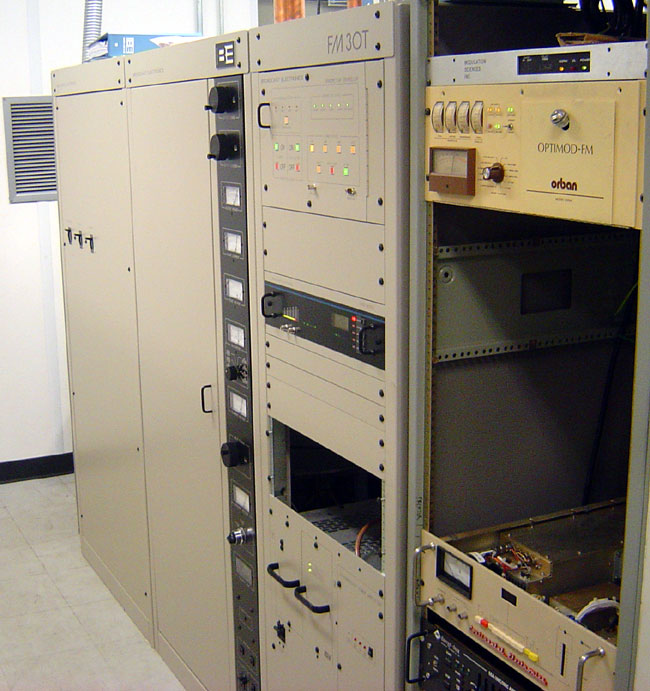
For some reason, the latest Broadcast Electronics tube-type transmitters seem to have very long tube life. I installed an FM20T at WYJB in Albany, New York, in early 2001 and it is still on the original tube, some ten years later. The same can be said for the 2005 FM20T and FM30T installation at WHHZ/WKZY, Gainesville, Florida. Those tubes show no sign of giving up anytime soon. I don’t know if that is an unusual trait of the transmitter or that particular tube.
WKZY, Gainesville, Florida
The above comparison seems to heavily favor a solid state transmitter. As a general rule, brand new solid state transmitters both AM and FM have advantages in almost every category except high power FM transmitters, where tube types still make sense. From a used transmitter standpoint, there is nothing wrong with a tube type transmitter, provided it has a solid state IPA. I have noticed the 4CX250B driver tubes most often used in FM IPA stages have markedly reduced reliability of late. I would also tend away from transmitter makes and models where the manufacture is no longer in business or no longer supports the product.