Since the FCC waved some of its rules regarding carrier power and carrier shift on the AM broadcast band, AM stations are now able to implement MCDL or DCC (Dynamic Carrier Control) technology to save money on their electric bills. This technology has the potential to save tens of thousands of dollars for higher-powered AM stations (high power=greater than 10 KW carrier level).
On a standard AM broadcasting station, the carrier represents two-thirds of the energy being transmitted, with the modulation index containing the other one-third. The carrier contains no information; it is simply there on the center frequency at the power level authorized by the station’s license. Thus, if the carrier can be reduced without affecting the quality of the broadcast reception, it will reduce to the overall power consumption of the transmitter. In areas where electric costs are high, the savings can be substantial.
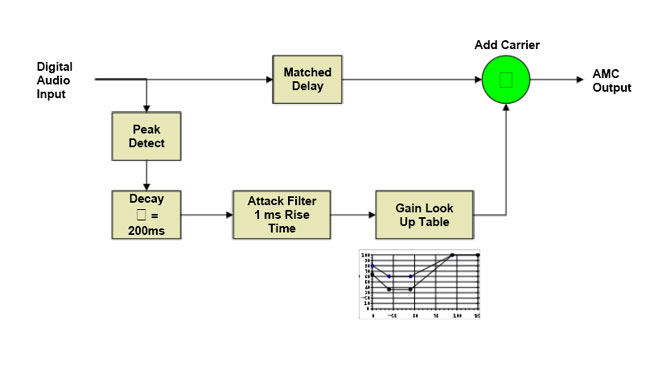
There are various ways to accomplish this. The first is called Dynamic Carrier Control (DCC), where the carrier voltage is reduced during moderate modulation levels (between 20-50%) and restored during peaks. This reduces the output power during average modulation, restoring most of it during quiet periods and peaks. The next is Dynamic Amplitude Modulation (DAM), which is similar to DCC. The most savings will be noted with less heavily processed programming such as talk radio because the higher the average modulation density is, the less the MDCL circuit reduces the carrier voltage level. The little graph in the diagram shows the reduction in the carrier voltage vs. modulation levels.
Nautel DAM block diagram, courtesy of Nautel, Ltd.
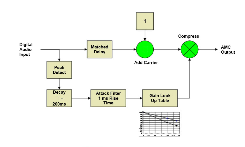
Finally, Amplitude Modulation Companding (AMC) reduces the voltage in both the carrier and modulation product during peaks. This results in better savings for higher-density modulation indexes. It is also the most transparent of the three schemes, as the carrier is restored to full power during periods of low or no modulation levels. During peak modulation, the reduction does not drop the power level below the un-modulated carrier level. The little graph in the diagram shows the reduction in the carrier voltage vs. modulation levels.
Nautel AMC block diagram, courtesy of Nautel, Ltd
Nautel has done extensive work on MDCL and includes several algorithms in their NX series transmitters. For older Nautel transmitter models such as ND, XL, XR, and the J-1000, there is an outboard exciter, which is in a one-rack unit chassis. Older transmitters may need a simple field modification to create a DC-coupled audio input. The cost for the upgrade is approximately $5,000 USD, however, check with the regional Nautel sales rep.
Once the system has been installed, there are several things to be aware of:
Modulation monitors may not work properly, especially older units, which will show significant carrier shifts and have carrier alarms. Belar AMMA-2 modulation monitor is specifically built to work with MDCL transmitters.
When making field strength readings, the MDCL circuitry must be turned off to get accurate readings.
For stations running IBOC, the amount of carrier power reduction may need to be experimented with, as the effect of the carrier reduction may cause the transmitter to exceed the NRSC mask.
Currently, only Nautel and Harris are selling MDCL transmitters. I spent several minutes poking around the Harris website and looking through their product brochures for the DX series transmitters and no mention of DCC o MDCL was found. I’d be happy to include any information from Harris if it were made available.
I figured if I have this problem, someone else probably has it too. We have a backup antenna on one of our towers. The station has a TPO of 28 KW, which is starting to get into the semi-serious level. This antenna is connected to Andrew 3-inch heliax that was installed in 1971. It has a spiral inner and outer conductor, which is no longer made by any manufacture of heliax.
We completely rebuilt the transmitter site a few years ago, moving a lot of things around. One part of the project was installing a coax port on the wall and moving all coaxial cables to that entrance. The main antenna is connected to Cablewave H50J coax. I ordered a new connector for that transmission line, no worries. When I cut the back up transmission line, I figured I could re-apply the old Andrew connector.
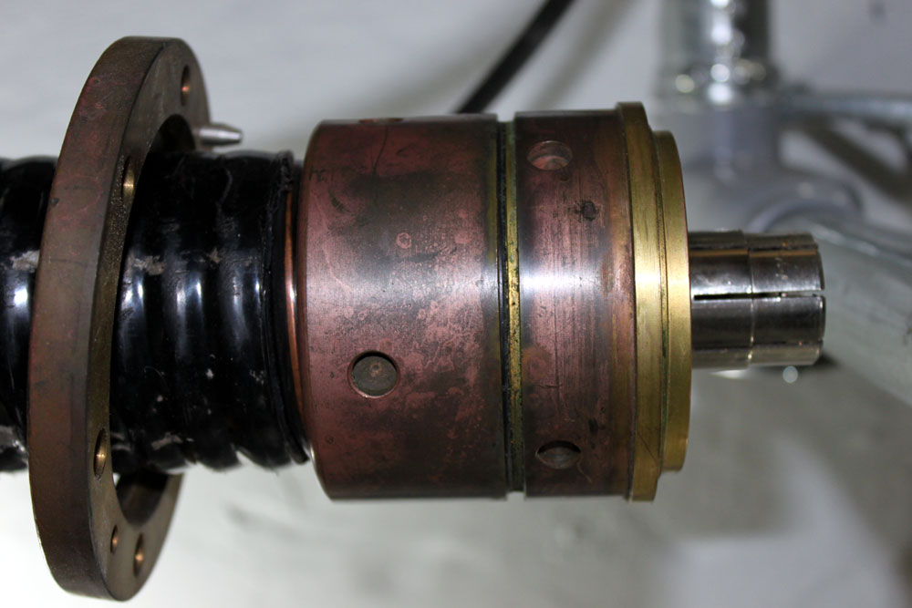
Andrew A909D type 78 AGM 3-inch coax connector
That is all fine, however, I removed the connector without reverse engineering it, that is to say, I didn’t pay close attention to how the inner and out conductors where cut, or how the jack was cut back. I will have to reverse-engineer the thing now.
Here are the steps I followed:
Check out the CommScope – Andrew website for documentation. A search shows they only have the current connector, which is nothing like this one and will not work with spiral conductors
Call Andrew and spend many minutes on hold or explaining to various helpers what I want. I was met with a universal “That is not an Andrew Part number,” or “Gee, I wish I could help but…”
Take the thing apart and begin measuring stuff with a ruler. Write everything down and draw out a diagram.
Trim off the excess cable then practice putting the thing together once.
Make the final cut and put the re-used connector back on the Andrew transmission line.
You can skip steps 1 and 2 since I already did them for you.
A few things to note:
The inner and outer conductors should be cut flush and as close to perpendicular as possible.
The inner conductor slug has a left-hand thread. This makes the slug tighten against the bushing.
The outer jacket is cut back about 2.5 inches
Place the EIA flange on the cable first, then thread the back nut onto the outer conductor, then thread the rubber gasket onto the outer conductor. The gasket is a tight fit, use petroleum jelly to lubricate it. This is a gas block connector, so special attention is needed with the gaskets.
The inner conductor has triangular pieces 1/8 inch deep cut around the diameter, the depth of the inner slug is critical to the connector going together correctly.
The inner conductor is folded inward over the end of the slug. Bushing, dielectric spacer, and EIA bullet are connected to the inner conductor slug and snugged down with a standard screwdriver
The outer conductor is nipped 1/8 of an inch around the diameter
The outer conductor is folded outward over the collect ring
Use some petroleum jelly on all the O rings
Carefully screw the connector together
Final tightening requires a special spanner wrench or attachments for a socket wrench. The tower crew had these in their shop.
If you have a spectrum analyzer, check its return loss and see what it looks like before slamming a full load on it. If not, turn things on and bring them up slowly. Feel the connector to make sure it is not getting warm. If there are problems, heat will be the first warning sign.
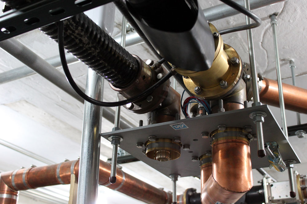
3 Inch coax patch panel
Once together, I ran the transmitters for a combined output of 10 KW and got about 50 watts return, which was much the same as it was before.
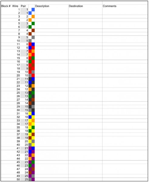
There are a myriad of details involved in building a studio, not to mention an entire facility. Getting everything down on paper before a single wire is pulled is one way to ensure that a neat, logical, and orderly product ensues. For wire run documentation, I like to use Excel spreadsheet templates that I came up with.
There are several different types of cable, from 25-pair ATT style to 16 or 24-pair shielded audio cable, to miscellaneous control cable, all of it has different color codes. I found the Belden Technical info website to be an excellent source for various color codes.
Doing neat work is the best way to keep things in order. Notice all the wires are labeled. All the ground conductors have heat shrink, which is required on insulation displacement terminations like 66 blocks, 110 blocks, and ICON terminations.
ADC ICON termination block
Once all the work is done, the wire run sheets are updated with changes and additions (there are always changes and additions) which will keep the documentation accurate.
I made up several templates with the wire color code, pair number, and cable information on each wire. This allows the wire man to quickly enter changes to the wire information on the sheet. At the end of the wiring project, these forms can be saved in several places, printed out, and placed in a book or however, the engineering manager wants to keep the information.
For 16/24 pair Gepco cable on ADC ICON Termination blocks, click here.
I say Gepco cable, any audio cable that is color coded with standard resistor color codes will work with these sheets, or the sheets can be adapted for use with other cables.
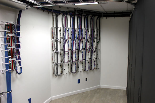
66 blocks audio and control for nextgen installation
This is a good installation. The company I work for has several wiremen that are artists and do excellent work. Notice there is adequate room and light to work on the wall. A dark, cramped area will lead to hurried work, poor workmanship, and mistakes in wiring.
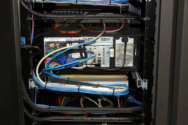
Automation computer on slide-out rack with cable management system
All the cables to the rack mount computers are neatly dressed, which allows easier service.
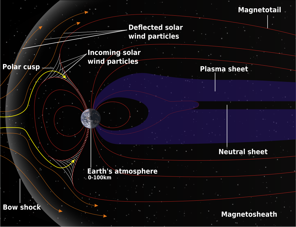
By now, you have heard of the great solar flare of 1859 that set telegraph wires afire across the US and Europe. This phenomenon was due to a large electromagnetic pulse from the earth’s magnetosphere interacting with the particles from a Coronal Mass Ejection (CME) caused by the solar flare. The long stretches of wire suspended above the earth acted like a large generator winding and cutting through the magnetic field, which in turn caused voltage (Electromagnetic force or EMF), which in turn, caused the fires.
In 1859 our understanding of electricity and magnetics is not what it is today, thus, the fires were likely caused by overloaded conductors without means to bypass excess electrical energy to ground.
Schematic of Earth’s magnetosphere, courtesy NASA
Fast forward to today. We are in the upswing of solar cycle 24, which is expected to peak in May of 2013. NASA predicts that this will be the lowest sunspot peak since 1907. That does not necessarily mean the coast is clear. Over the last 11 years since solar cycle 23 peaked, computers and electronic automation have proliferated exponentially, becoming the norm. Things like GPS not only guide clueless travelers where to turn but also sync up all those cellular telephone transmitters with timing signals. IP networks, SCADA, telephone networks, and so on all run on some form of CPU. Newer Energy Star appliances like toasters and refrigerators also have CPUs. That technology has yet to experience a large electromagnetic pulse (EMP) in the real world. Things could indeed get hairy if a moderate to large class X solar flare generated a CME that was polarized correctly to interact with Earth’s magnetic field and cause damage at ground level.
Solar flares and CME are slow-moving events, with 1-2 days warning before the effects of a CME reach Earth. One can stay apprised of solar flares and other solar activity by subscribing to NOAA Space Weather Prediction Center’s email service.
HEMP Mechanism for 400 kM high altitude burst
Of greater concern is other sources of EMP like high altitude nuclear explosions (HEMP). Those types of events, while rare, can happen. The good news is, the defense mechanisms for solar flares, high-altitude nuclear bursts and lightning-induced EMP are the same. They are effective grounding, shielding, filtering and surge suppression.1 Of the three EMP scenarios, high altitude nuclear burst has the tightest design spec, so creating a building that incorporates the ideas in MIL-STD-188-125-1 specifications is a good start.
The question becomes, is all of this really necessary. It depends on how important it is to radio station ownership to remain on the air during such an event. Based on historical information and global geopolitics, the probabilities of such an occurrence are:
Lightning strike – 1:1 Any radio station that has a tall structure, particularly a steel tower, will get struck by lightning, perhaps several times per year depending on the region.
Large Class X solar flare resulting in damaging CME – 1:21 Since 1859, there have been seven solar flare events that have disrupted communications or power systems on Earth. This is a bit misleading since 6 of the 7 events have occurred in the last 22 years, making the real probability more like 1:3.6
High Altitude EMP – 1:30 Based on seventeen high altitude tests carried out by the US and USSR in 1962, the growing nuclear proliferation and a June 2005 Reuters article “Experts warn of substantial risk of WMD attack” in which the author stipulates a thirty percent risk of a nuclear attack of any type in the period of 2010 to 2015.
EMP Theory
High altitude nuclear burst EMP has three components; the fast component (20/550 ns pulse) is an electromagnetic shock-wave, the medium-speed component (1.5/5000 μs pulse), and the slow component (0.2/25 s pulse) resulting from the expansion of the explosion’s fireball in the Earth’s magnetic field.1 Compare that to a lightning strike, which typically has a 1.8 µs rise time. That means the first pulse frequency is from about 72 to 200 MHz, the second pulse frequency is from about 800 Hz to 2.5 MHz and the third pulse is basically DC and affects mostly long wires. Thus, any shielding, grounding and suppression needs to consider the highest frequency down to about 10 KHz.2
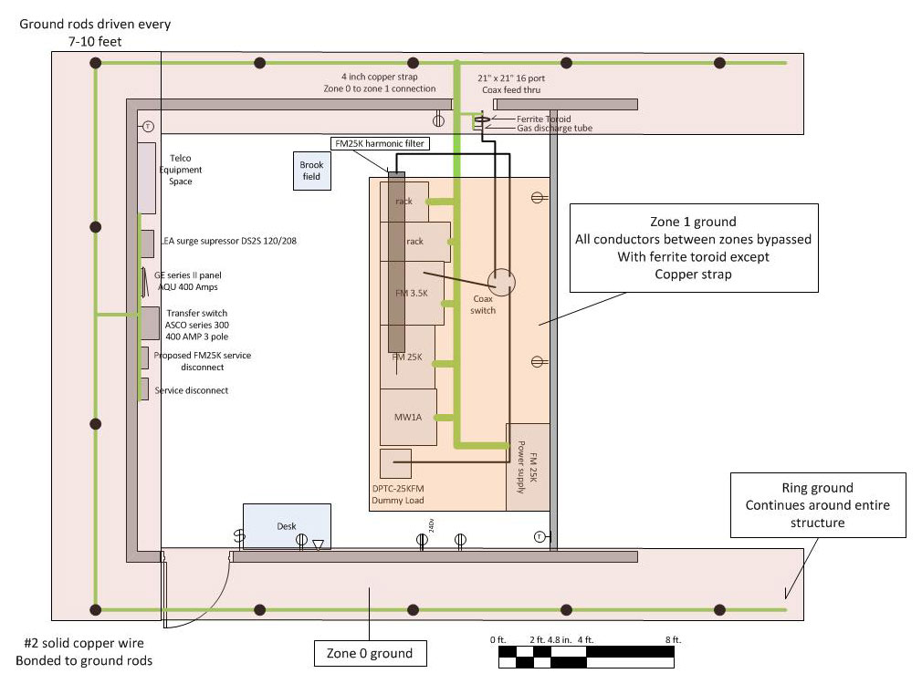
The rise time to frequency comparison is an important consideration in the design and construction of grounding systems. Grounds need to present the least amount of inductance possible. This means using solid, not stranded wire, keeping bends to a minimum and where required, use long radiuses. Bond all junctions by welding, exothermic welding or soldering. Use a single point ground system. Zone grounding should also be employed. The definition of zone grounding is concentric grounding areas connected to each other by a single low-inductance ground conductor.2 The idea of isolating grounds by use of a ferrite suppressor may seem odd, however, if there is a separate RF ground, tied together with the building ground using wide copper strap laid on the floor, this will minimize ground system “reception” of incoming EMP.2,3
Zone grounding diagram
Shielding means surrounding the protected equipment with a conductive material such as copper plate, aluminum plate, copper mesh, aluminum mesh, brass mesh, steel plate or steel mesh.1,2 There are advantages and disadvantages to each. Seams should be welded to prevent “leaks.” Doors need to have finger stock or metal compression gaskets to ensure proper sealing of opening. Other openings for ventilation, cable ingress, etc. need to be “significantly” less than one wavelength. MIL-STD-188-1 gives the allowable opening size of 10 x 10 cm or 3.9 x 3.9 inches. If openings in the shield become greater than approximately wavelength/6 meters (at 250 Mhz, about 8 inches), significant fields can penetrate to the interior.2
Suppression deals with those connections to the areas outside of the facility. These include incoming electrical service, data service and RF transmission lines to and from antennas. Since the fast component of the HEMP falls within the VHF spectrum, FM broadcast installations are particularly vulnerable. Suppression devices for incoming AC power are readily available from commercial sources and are well proven. LEA makes a series surge suppressor that uses a combination of fast acting silicone diodes, MOVs, and an LC filter made up of series inductance and parallel capacitance to ground. The LEA DYNA family series surge protectors have a system response time of less than one nanosecond and are tested to greater than 1,000 operations.4 The response time depends on a good, non-inductive ground connection.
LEA DYNA systems series surge protector
Suppression for incoming RF and data cables is more difficult because the normal operating frequencies fall within the HEMP rise time frequency. Incoming data at a transmitter site usually consists of a DS-1 circuit however, larger capacity circuits are sometimes used. Fiber optic cables are immune from HEMP as they have no metal conductors. Copper data lines must have a data line surge suppressor between the TELCO demark and the CSU.
RF cables must have their shields ground to the zone 0 ground, then go through a ferrite toroid to add inductance to the outer shield and isolate it from the zone 1 ground. After the ferrite toroid, a gas discharge type inline surge suppressor should be used. These come in a variety of configurations, frequency band and power levels. It is best to keep the suppressor rating as close to the peak carrier power as possible, affording the most protection to the transmission equipment.
Design and implementation of EMP hardened facilities
Of the four strategies for mitigating HEMP; Grounding, Suppression, filtering and shielding, shielding is the hardest and most expensive to implement. Good grounding should be included in any good radio station design same as suppression and filtering.
Grounding. Grounding for a transmitter site must include an outside ring ground around the periphery of the building.2 This is bonded to several ground rods installed at regular intervals. The ground is brought into the building and all coax shields, electrical service entrance, TELCO equipment, suppression equipment and safety grounds are connected to it. This forms the zone 0 ground. One conductor then goes to the zone 1 ground which is the transmitters and racks. Any other conductors at any potential that go from zone 0 to zone 1 are bypassed at EMP frequencies by use of ferrite toroids or other high mu ferrous metal filters. Inductors may need to be bonded to ground to prevent saturation. At studio locations, the building electrical safety ground should be evaluated for adequacy. Additional grounding may need to be installed depending on effectiveness of existing ground. Any outside antennas, supporting structures, satellite dishes and generators need to be bonded together and grounded to the building electrical grounding system. Studios and engineering rack rooms need to be bonded to the ground using star topology. Facilities that are not adequately grounded should be retrofitted.
Suppression and filtering. Good surge suppression and filtering should be a part of all transmitter and studio site designs. Hanging a few MOVs off of the service panel is not enough to prevent damage to a facility. All incoming lines from the street; electric, telephone, and cable need to have surge suppression connected and be bonded to a low inductance path to ground. The only exception to this is fiber optic, which is immune to the effects of EMP. Additional layers of filtering for sensitive, mission-critical computer systems such as FERUPS, shielded category wiring that is properly installed, etc. Facilities that do not have adequate suppression can be retrofitted.
Shielding. Shielding is the most expensive, time-consuming, and difficult to install correctly. The High Altitude nuclear test Starfish Prime in July of 1962 produced a field of 5600 V/m in Honolulu, some 1300 KM away from the blast. Building a shielded structure against those intense magnetic and electrical fields is very difficult. Attenuating the field through layers of shielding is the most effective means provided the distance between the shields is wavelength/6 or more (about 27 inches at 72 MHz) to prevent coupling.2 For example, using a concrete structure with steel mesh creates 35-40 dB of attenuation in zone 0, and a well-designed transmitter with good RF shielding in its cabinet design creates a shield for zone 1. Equipment racks can also be used to create shielding zones by using copper or brass mesh with good metal-to-metal contact around the front and back doors. At studio locations, engineering rack rooms should have copper or brass mesh embedded in the wall structure to create a shield. This will create a safe area to locate computer file servers, routers, switches, STL gear, satellite receivers, and the like equipment. Layered shielding with the use of metal, gasketed door will improve shield performance. Retrofitting shielding is more difficult to accomplish than grounding and suppression. It is best done in new construction. There are many different ways to accomplish even moderate shielding, which may serve well for lightning and solar flare-induced EMP.
From personal experience, investing an extra $10-20K in grounding and suppression at a lightning prone transmitter site in Florida solved all of the issues at that site. Prior to installing the ring ground and bonding, the transmitter was knocked off the air several times per year. Since the work was done in 2005, there has not been one lightning related outage at that site.
References: 1. Protection Technology Group, System Approach to EMP Mitigation, February 2011 2. US Army Corps of Engineers, Engineering and Design – Electromagnetic Pulse (EMP) and Tempest Protection for Facilities EP 1110-3-2, December 31, 1990 3. US Department of Defense, HIGH-ALTITUDE ELECTROMAGNETIC PULSE (HEMP) PROTECTION FOR GROUND-BASED C4I FACILITIES PERFORMING CRITICAL,TIME-URGENT MISSIONS, MIL-STD-188-125-1A, February 15, 1994 4. Protection Technology Group, Modular Hybrid Series Connected Surge Protection Device LEA DS21 data sheet, 2010