Alternate title: Building and ATU in a truck body toolbox.
Alternate title II: I should get paid extra for this shit.
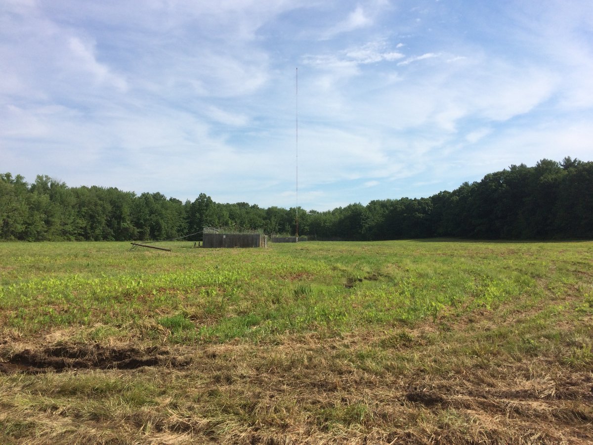
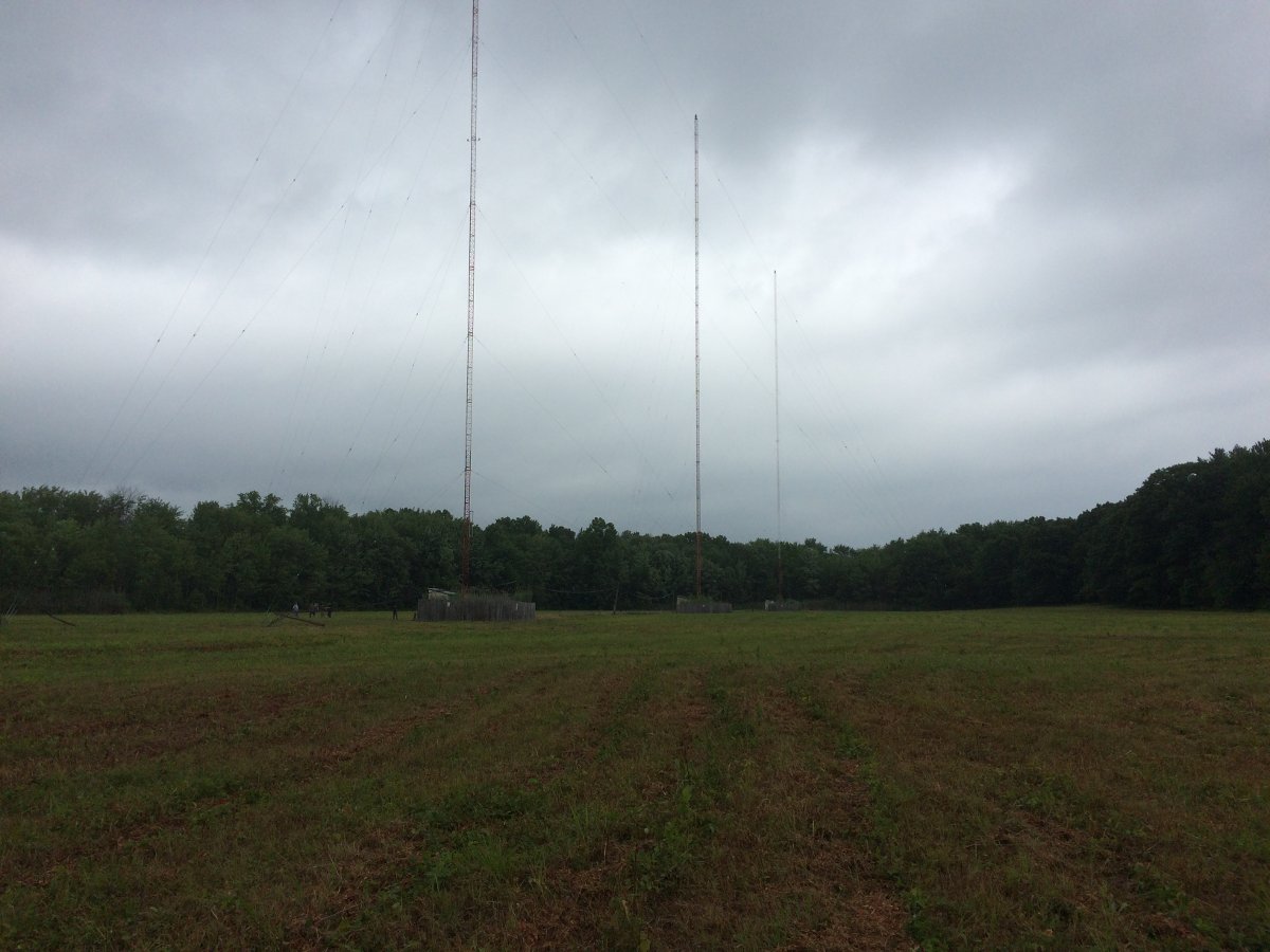
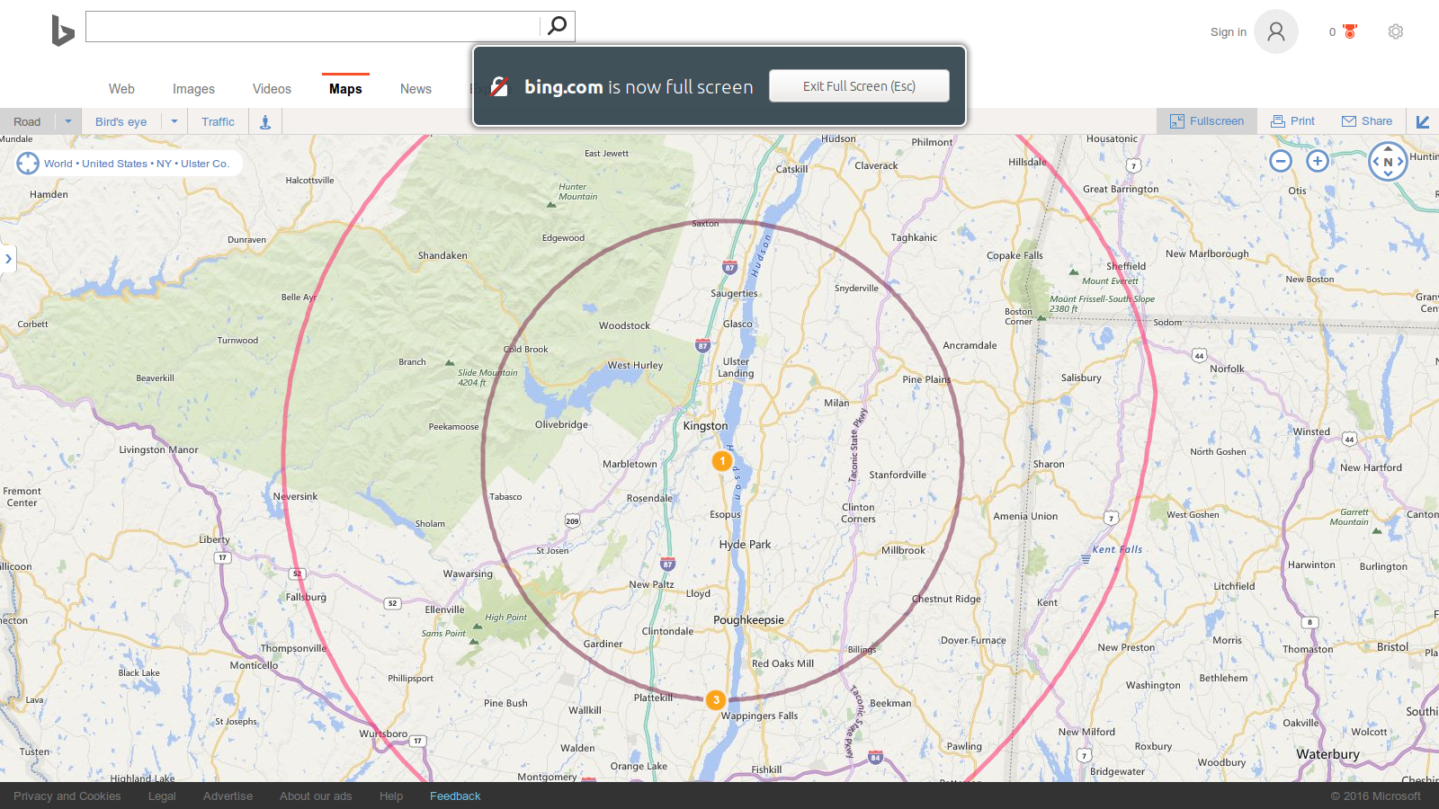
There is an AM radio station that is near death but the owners do not want it to go away. Nor do they want to spend very much money to keep it around, thus the dilemma. At the transmitter site, there is a multitude of problems; leaking roof, very old rusty ATU, rotting support posts and transmission line bridge, equipment racks rusting out, nothing is grounded properly, the building is full of junk, snakes, and mice have moved in. To further complicate things, the tower and transmitter building serves as an STL relay point for two of the market’s FM stations. There is also two translators with antennas on the tower. The ATU and tower light choke box are rusting through, which is causing arcing and broadband RF noise that is interfering with the FM station’s STL receiver. There was a homemade isocoupler for one of the translators that were allowing AM RF back into the building which was creating havoc with everything. Because of this, the AM station is currently silent. In short, it is a mess.
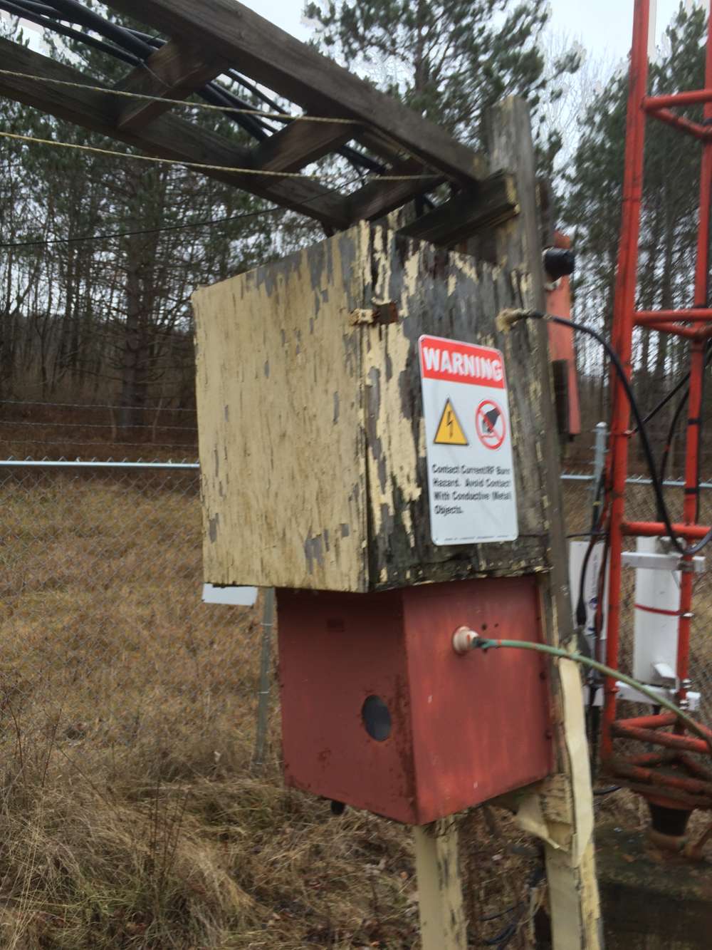
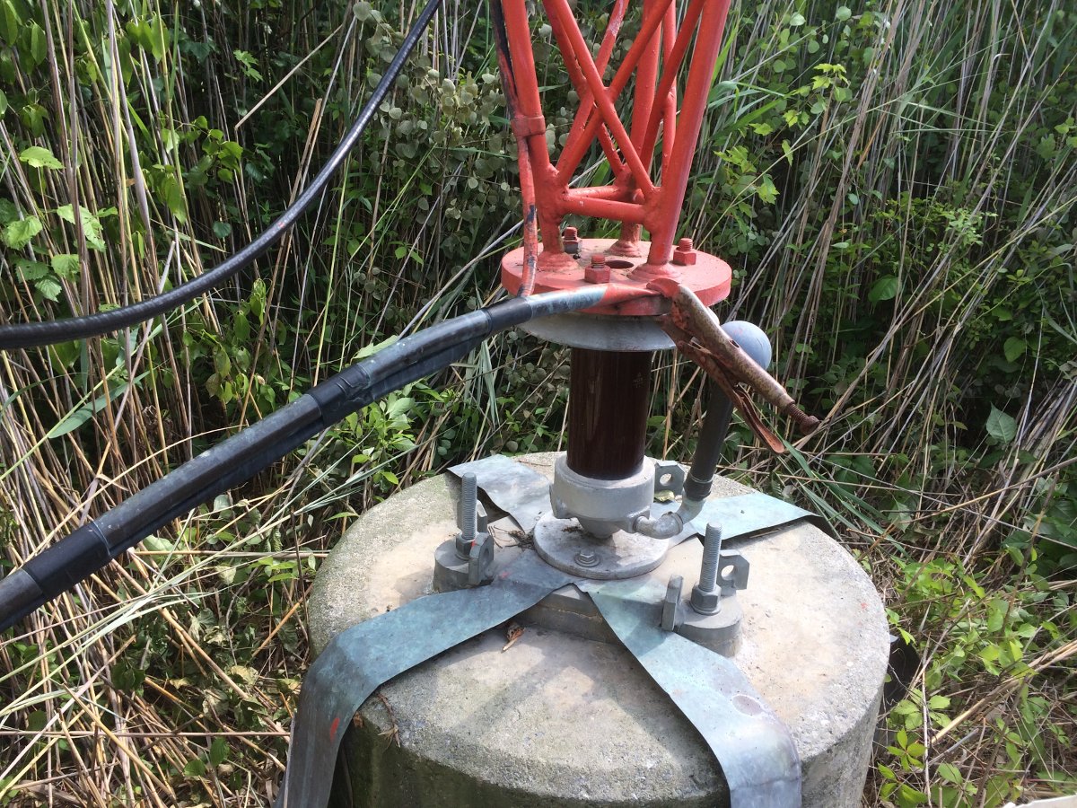
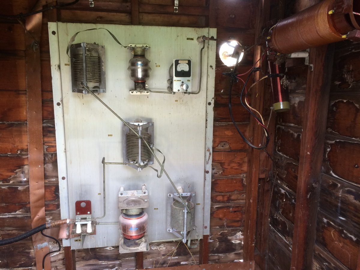
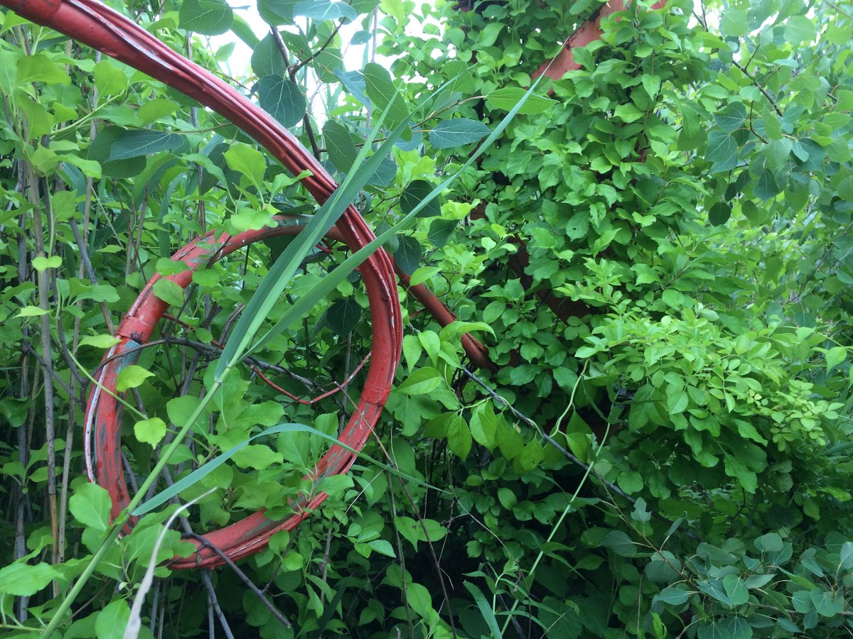
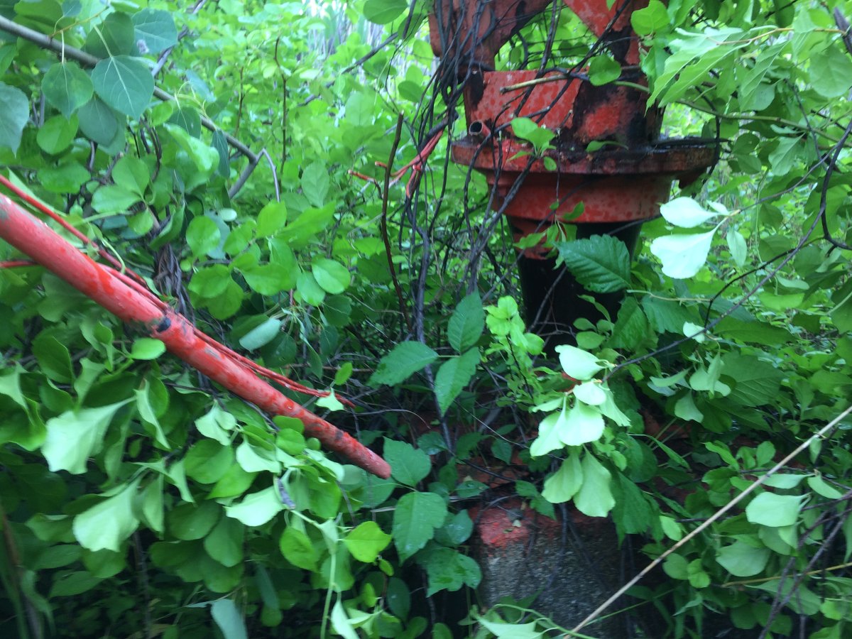
The red box on the bottom is the ATU, the plywood box on the top with the peeling yellow paint is the homemade isocoupler, and the tower light choke box is behind the isocoupler.
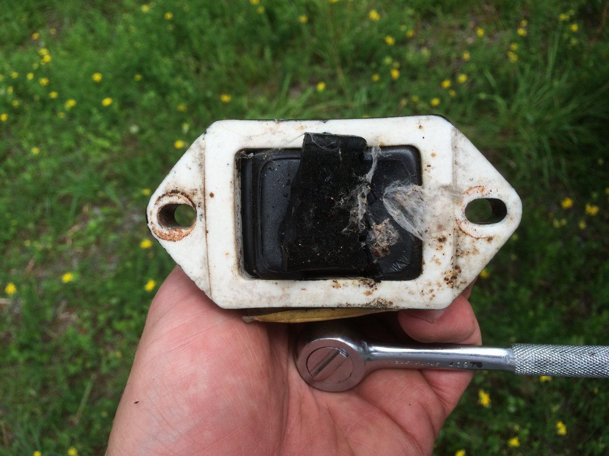
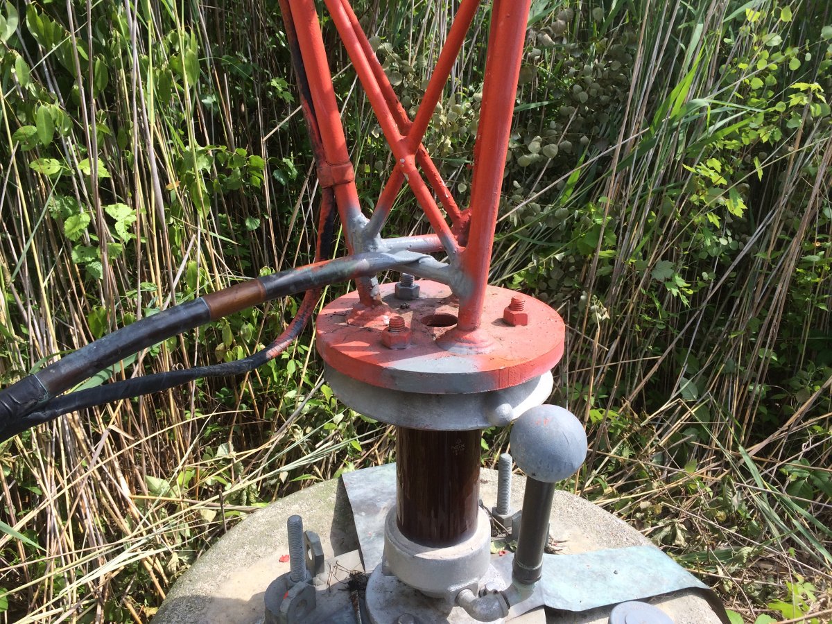
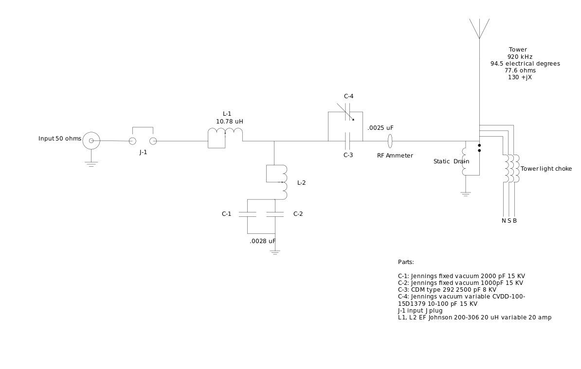
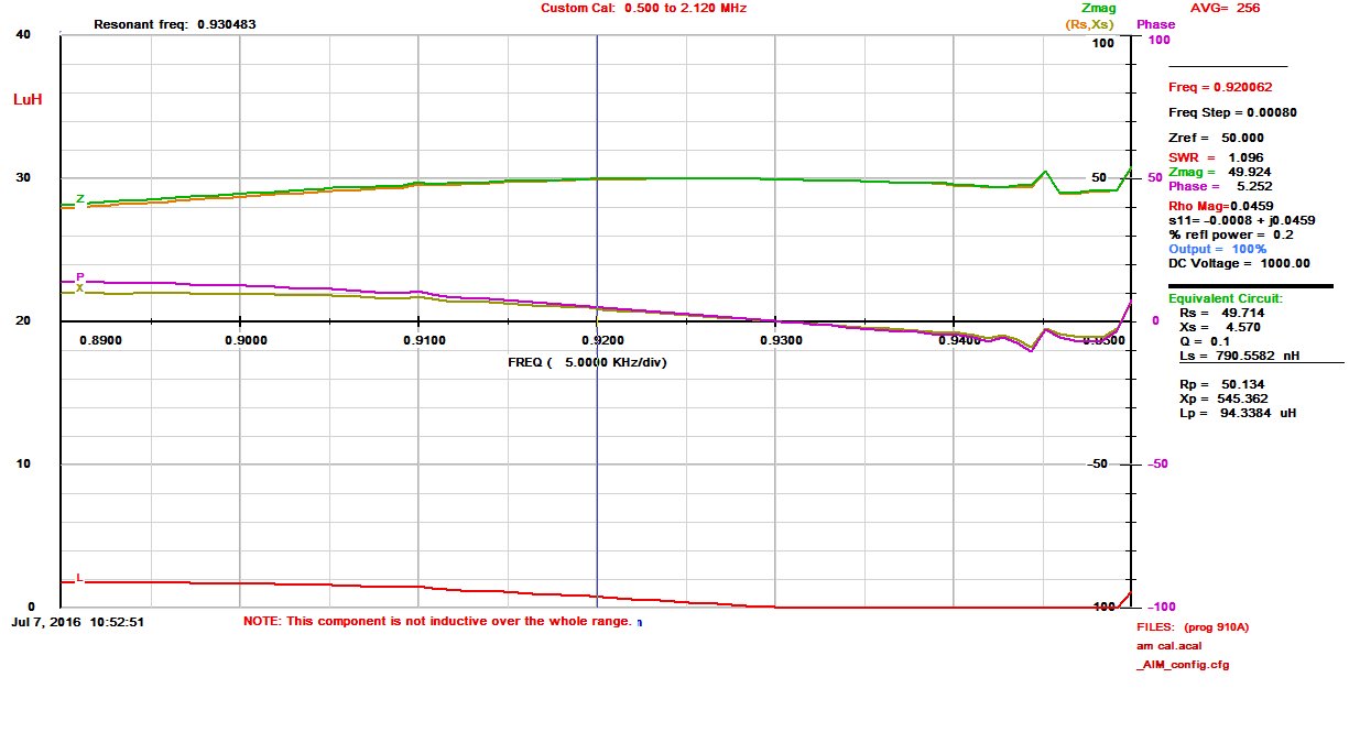
This was the capacitor that was feeding the antenna, .0041uf, 10KV 8 amps.
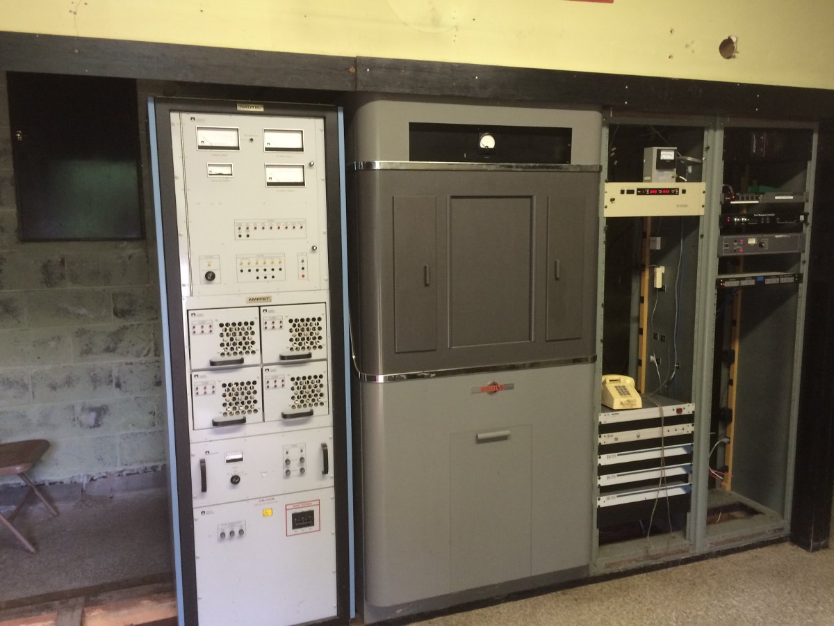
We started remediation on this last February, which is not the optimum time for replacing rotting wooden posts. However, we were able to clean out the building. The leaking roof has been repaired. I was able to find a few old racks from a Schafer Automation system to replace the rusted-out original racks. I began the process of grounding the equipment racks, the incoming transmission lines for the STL, etc.
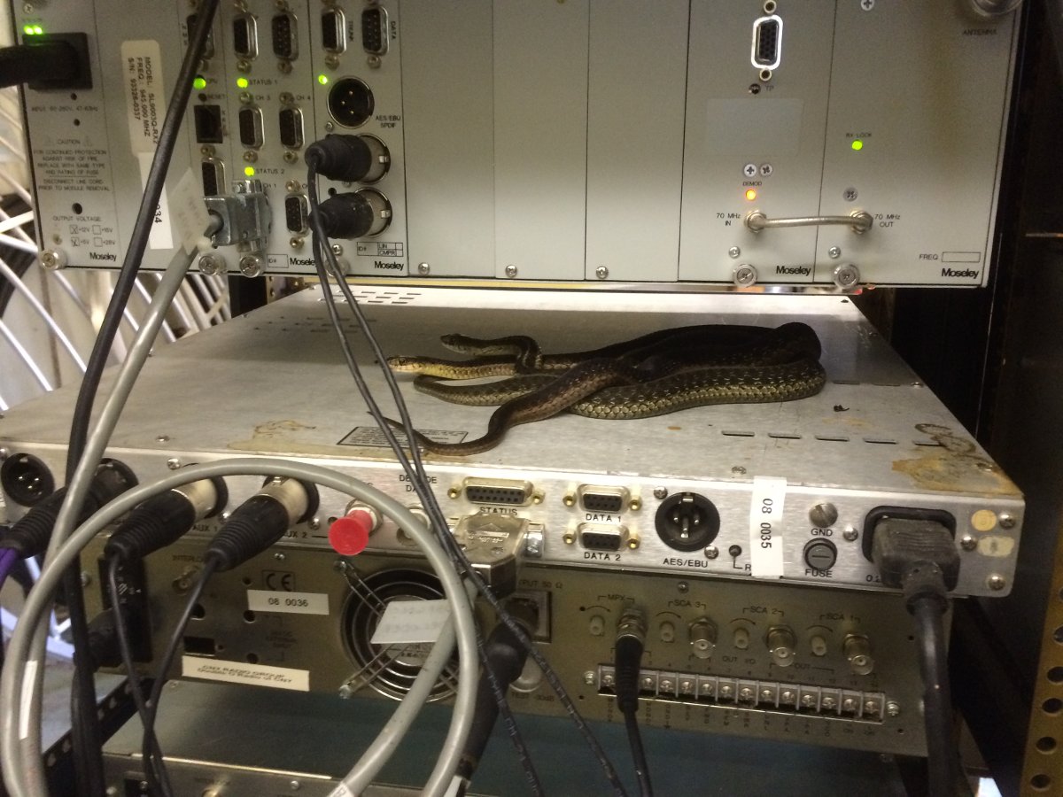
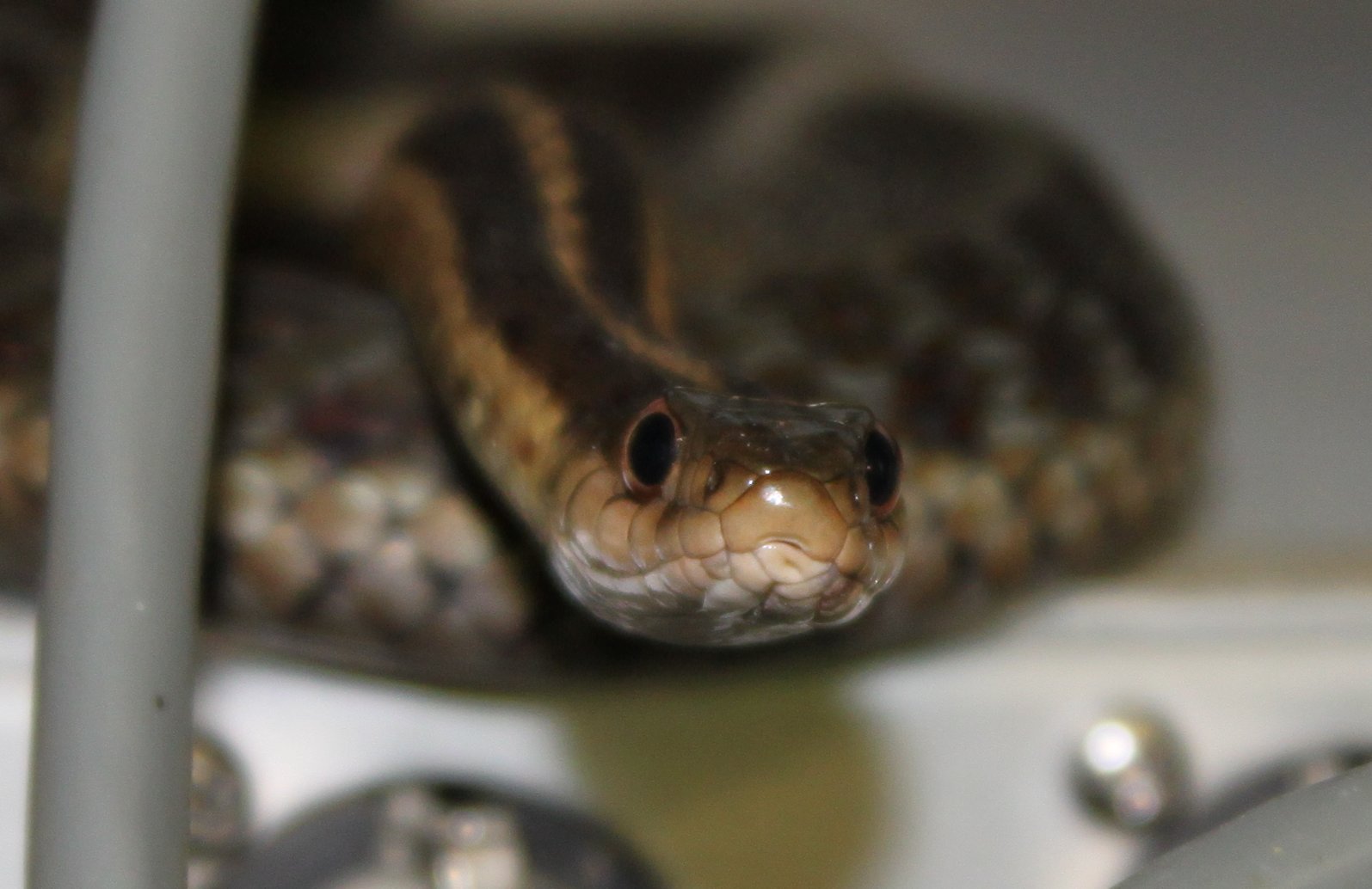
We will have to find out how they are getting in, the plug up those holes.
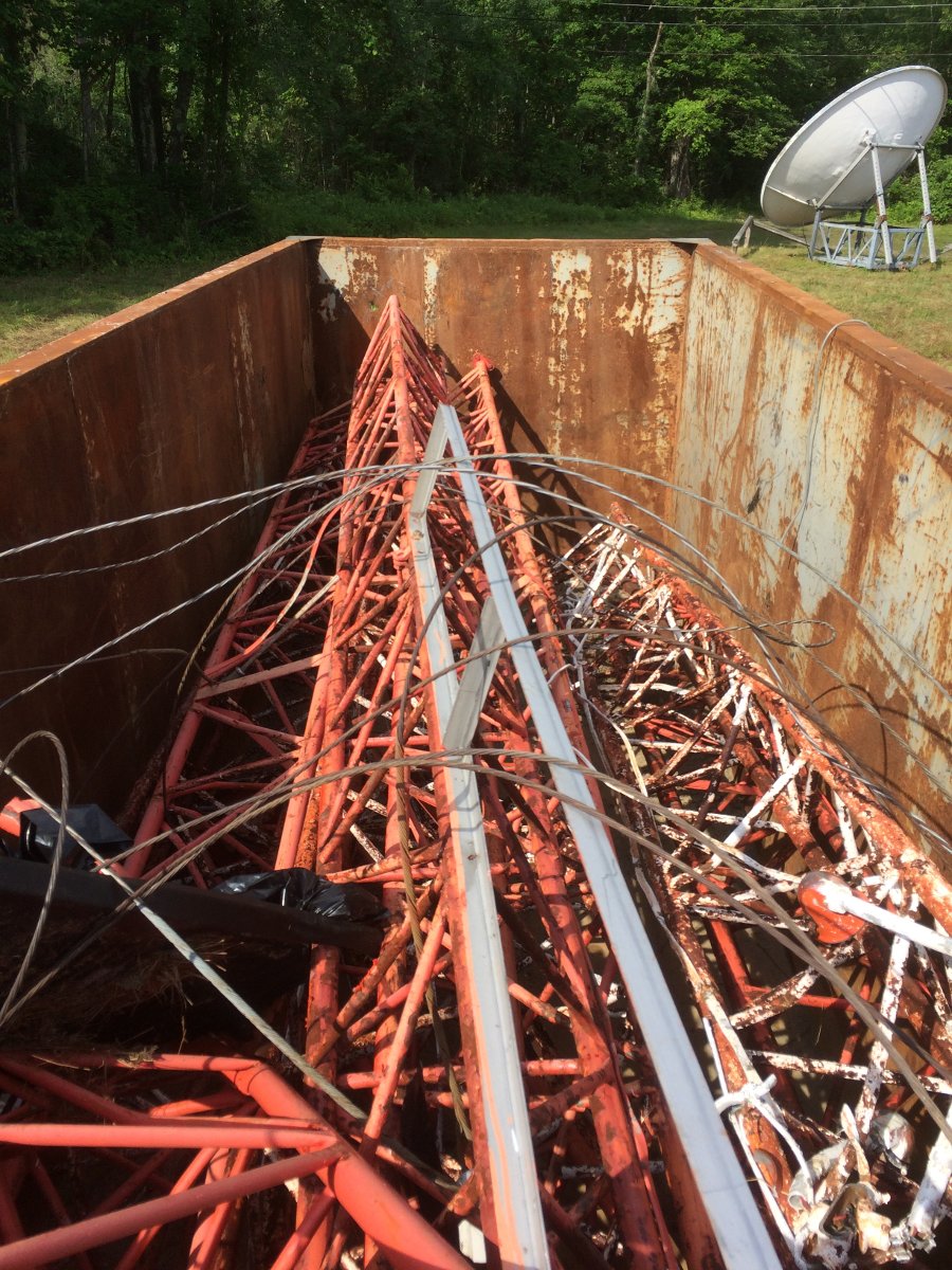
Then there were the ATU and tower light choke enclosures. Original to the 1952 sign-on, they were past their serviceable days. Since this is all being done on a budget and nobody wants to spend money on an AM station that has little or no listeners and even less revenue, we had a problem.
Then somebody suggested building an ATU in a truck body tool box. Well… This isn’t the Meadowlands, so if there are no other alternatives then okay, I guess. Off to Amazon to order a toolbox. This particular unit seems fine, my only comment is on the gauge aluminum (or aluminium if you prefer), which is slightly thin for holding up all those parts.
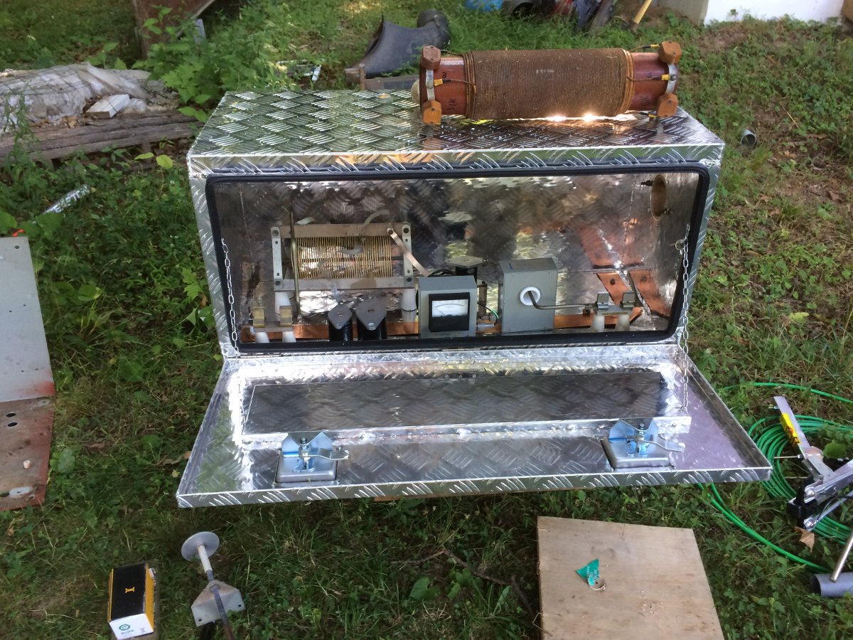
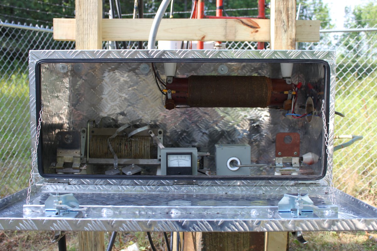
Still, the box itself is nice enough and certainly better than the old one. I was able to reuse the inductor and the Delta current meter but the old Sangamo capacitors crumbled in my hands when I removed them. I also saved the feed through bowls, J-plugs, and other parts. I used some copper strap to run a good RF ground from the input to the ground connection. Overall, I am pretty pleased with the finished product. It is a little bit tight in there, but this station only runs 1 KW, so it should be fine.
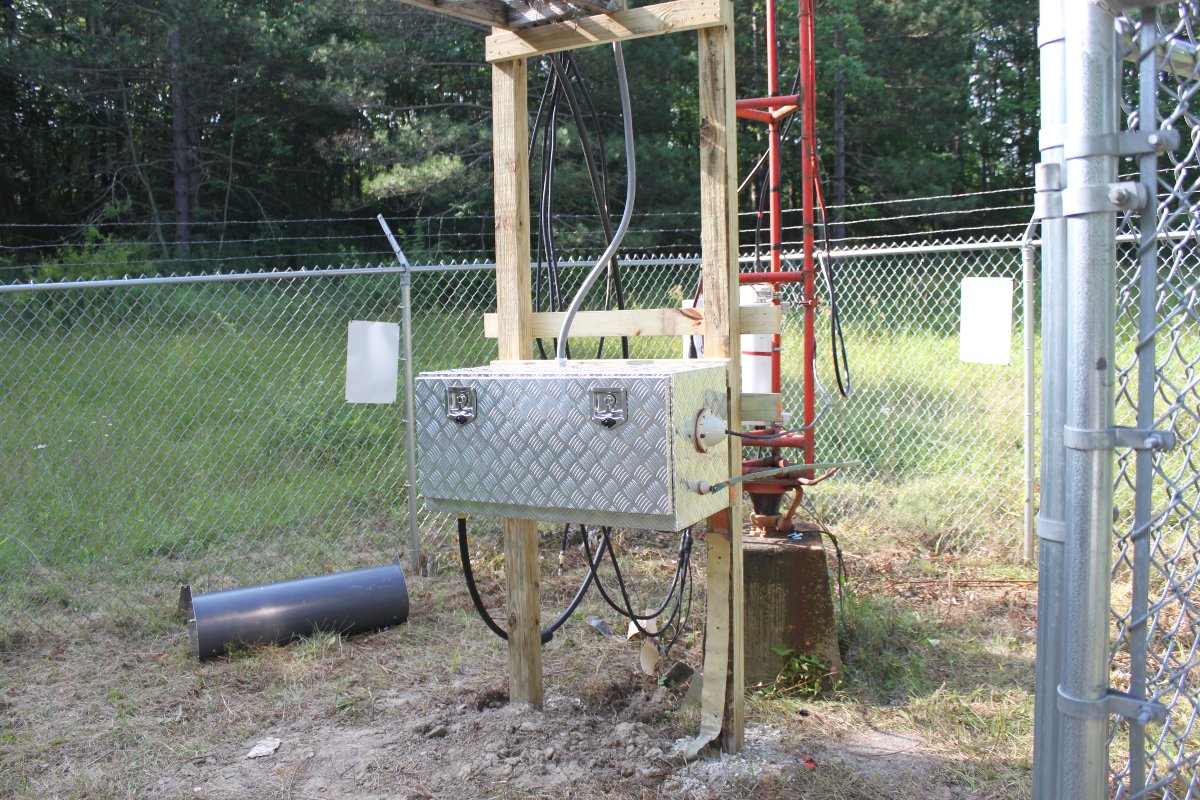
So, new pressure-treated posts were installed, the box was mounted and the transmission line was connected.
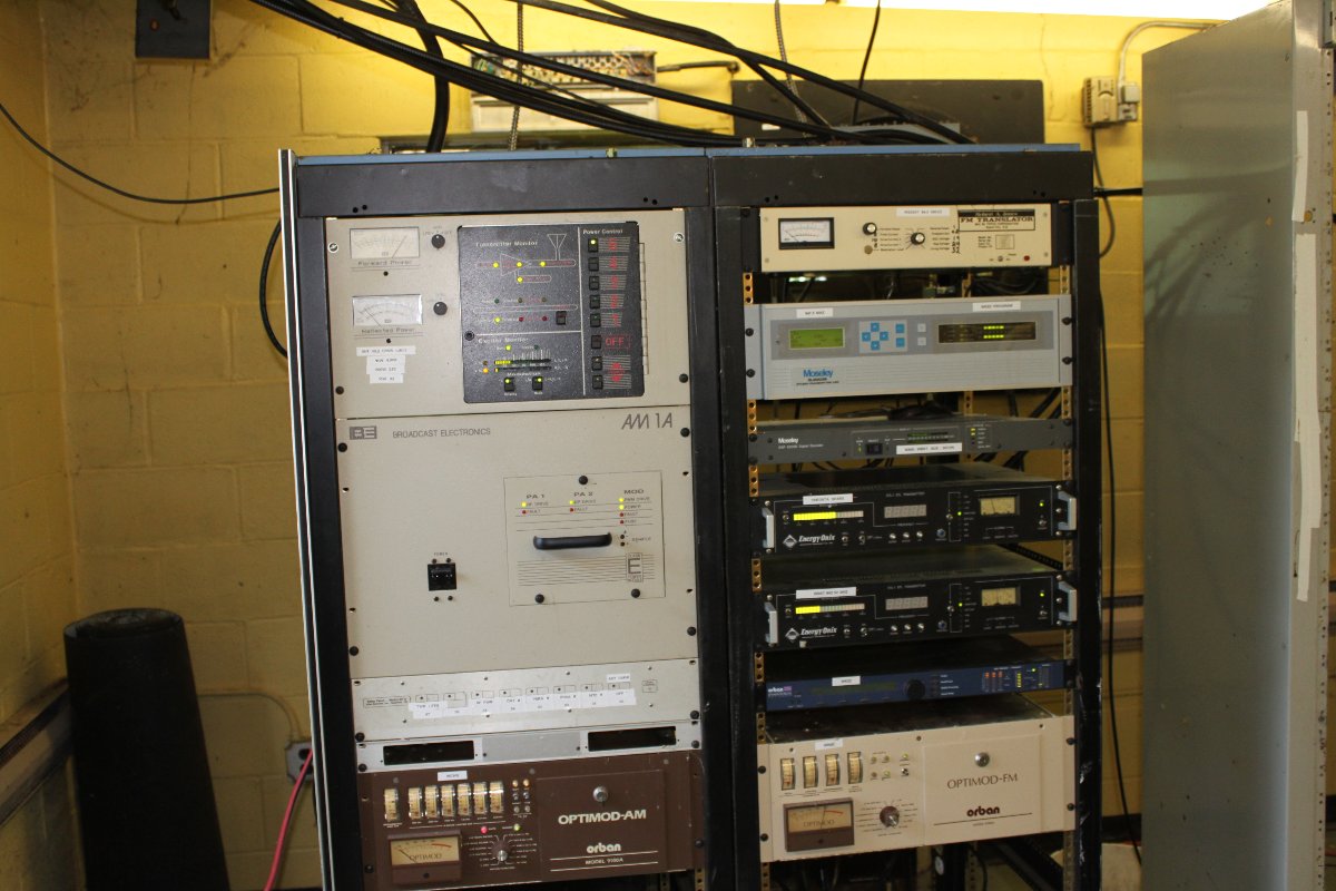
The reused racks are old but serviceable and a big improvement over the old, rusting-out racks. I was able to bond each rack to the ground strap that was used to connect to the RCA BTA-1 transmitter. There is one more rack to install to the right of these two. That should give us more than enough rack space for this site.
The station is back on at full power and not interfering with the FM STLs or the translators. You can actually touch the rack and not get an RF burn!
We are also working on an air conditioner.
Other work at this site; cleaning out the building, replacing the tower light photocell, installing a ground buss bar, some STL lightning protectors, dressing the transmission lines, etc. It is a work in progress.