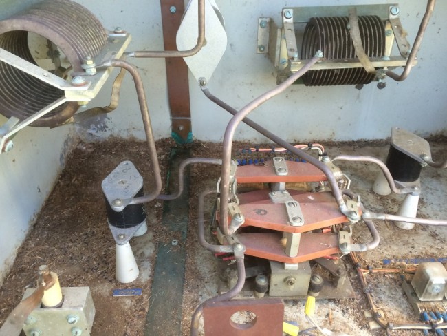
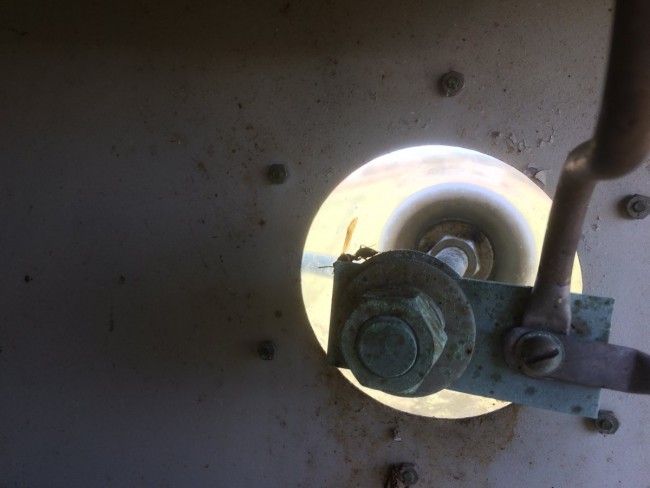
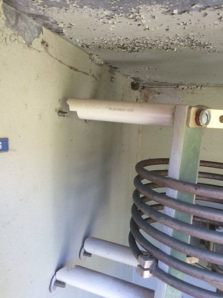
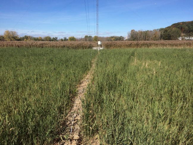
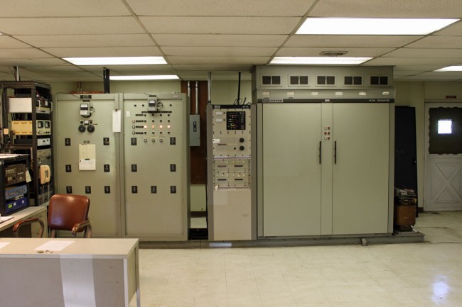
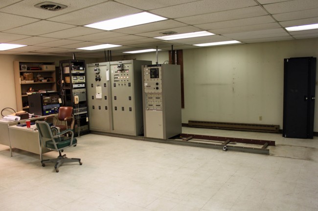
I was at a transmitter site a few days ago scrapping a Continental 814-R1 transmitter and started thinking (always a dangerous thing) about how many of these units I have decommissioned over the years. It turns out, quite a few:
| Make/Model | Year new* | Year removed | Station | Disposition |
| GE BT25A | 1948 | 1994 | WPTR | Donated/scrapped |
| Gates BC5P | 1960 | 2004 | WWLO | Donated |
| Harris MW5A | 1982 | 2000 | WLNA | Scrapped |
| Gates BC1T | 1961 | 2001 | WLNA | Donated |
| Harris FM20H3 | 1972 | 2001 | WYJB | Scrapped |
| RCA BT1AR | 1960 | 2001 | WROW | Donated |
| Harris BC1G | 1972 | 2001 | WDFL | Abandoned |
| Harris FM20H3 | 1971 | 2005 | WHUD | Scrapped |
| BE FM30A | 1988 | 2005 | WHUD | Cannibalized |
| Harris FM5G | 1972 | 2008 | WSPK | Scrapped |
| Mc Martin BF3.5K | 1976 | 2011 | WCTW | Scrapped |
| RCA BTF-10ES | 1978 | 2011 | WRKI | Scrapped |
| Gates BC1T | 1964 | 2011 | WINE | Scrapped |
| Continental 315F-R1 | 1985 | 2013 | WVMT | Donated |
| Collins 813F | 1975 | 2014 | WKXZ | Scrapped |
| RCA BTA1AR | 1965 | 2014 | WCHN | Scrapped |
| Collins 813F2 | 1978 | 2015 | WKXZ | Scrapped |
| Collins 830D-1A | 1968 | 2014 | WKXZ | Scrapped |
| Harris FM20H3 | 1972 | 2013 | WYJB | Scrapped |
| Harris BC5HA | 1973 | 2013 | WROW | Scrapped |
| Harris FM10H | 1971 | 2013 | WMHT-FM | Scrapped |
| Harris FM2.5H3 | 1973 | 2015 | WEXT | Scrapped |
| Mc Martin BF3.5K | 1972 | 2014 | WSRK | Scrapped |
| CCA FM5000G | 1980 | 2015 | WTBD | Scrapped |
| RCA BTF1E | 1972 | 2016 | WZOZ | Scrapped |
| QEI 695T3.5 | 1996 | 2015 | WBPM | Scrapped |
| QEI 695T5 | 1996 | 2015 | WBPM | Scrapped |
| Harris HT3.5 | 1997 | 2015 | WUPE-FM | Scrapped |
| Harris Z5CD | 1997 | 2015 | WXPK | Cannibalized |
| Energy Onix SSA1000 | 2000 | 2015 | WDHI | Cannibalized |
| Harris MW1 | 1982 | 2016 | WPUT | Abandoned |
| Mc Martin BF1K | 1982 | 2016 | WSUL | Scrapped |
| Mc Martin BF3.5K | 1982 | 2016 | WSUL | Scrapped |
| Continental 814R1 | 1980 | 2016 | WDBY | Scrapped |
| Broadcast Electronics FM35A | 1986 | 2017 | WEBE | Cannibalized |
| CCA FM-1000D8 | 1973 | 2018 | WDLA | Scrapped |
| Collins 828E | 1978 | 2018 | WSYB | Scrapped |
| Gates BC-1H | 1971 | 2018 | WHUC | Scrapped |
| Gates BC-1J | 1954 | 2019 | WBEC | Scrapped |
| Gates BC250GY | 1969 | 2019 | WSBS | Scrapped |
*In some cases the “Year New” is a guess based on when the station went on the air. Before you write me and say “But model XYZ transmitter wasn’t made until 19XX, I did not look at every nameplate and write all the information down as I did this.
Like everything else, there is a process to this.
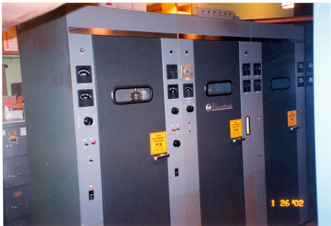
First of all, if the transmitter was made before 1978, the possibility of PCB capacitors and transformers exists. In the case of the GE BT25A, massive amounts of PCBs needed to be disposed of properly. According to current federal laws, ownership of PCBs and PCB-contaminated items cannot be transferred. Thus, the transformer casings were cleaned out and taken to Buffalo to be buried in a PCB-certified landfill. Otherwise, most other transmitters, such as the RCA BTA-10, may have a few PCB capacitors in them and perhaps the modulation transformer. Those items can be disposed of by calling an authorized environmental disposal company like Clean Harbors.
The rest of the transmitter is stripped of any useful parts. Things like vacuum variable capacitors, rectifier stacks, blower motors (if they are in good condition), HV power supply contactors, unique tuning parts, whole control and metering boards, tube sockets, etc.
The remaining carcass is then disassembled and hauled off. I got a guy that will do this for relatively little money. He takes the transmitter back to his warehouse and cuts it up, sorts all of the various metals out, then takes it to the scrap yard. This includes things like cutting all of the windings off of transformers and power supply chokes, sorting out the brass and copper tuning parts, etc.

