The head smasher

I have worked in hundreds of transmitter sites over the years; AM, FM, TV, HF, Two way, Paging, Cellular, etc.  So many, I have lost count.  The one thing that is always annoying is equipment that is suspended from the ceiling at just the wrong height, AKA: The Head Smasher.  It does not matter if warning signs are posted, I’ve seen them marked with black and yellow caution tape, and so on.  If it is installed low enough for somebody to hit their head, contusions will result.
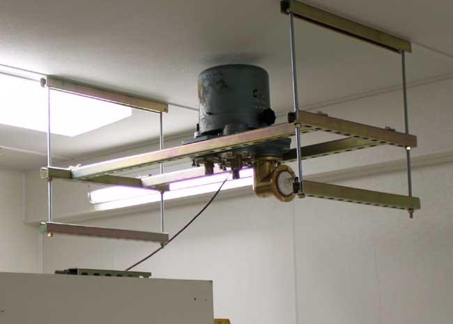
3 1/8 inch motorized coax switch mounted

Thus, when it came to installing this motorized 3 1/8-inch coax switch, there was only one way to do it.  Installing it the other way would result in a head smasher behind the backup transmitter because the ceilings are low.  The problem with this style of mounting is how to get to the motor and clutch assembly for servicing.  There is but one inch of clearance between the top of the coax switch and the transmitter room’s ceiling.  If servicing is needed, the entire switch would need to be removed, resulting in lots of extra work and off-air time.
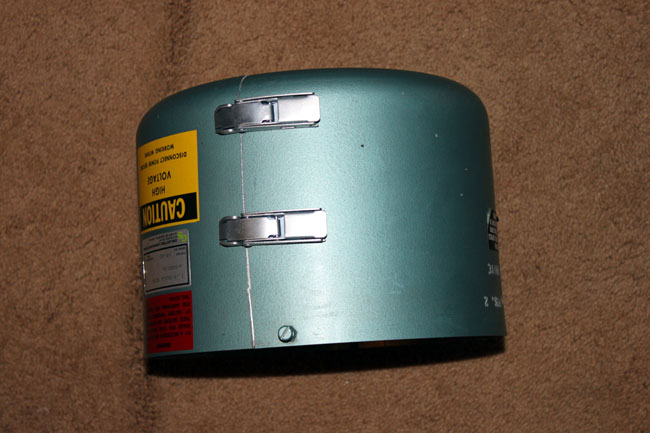
3 1/8 inch motorized coax switch cover

So, an idea was formed.  Why not cut the switch cover in half and put some hinges on it.  The cover itself is made of aluminum.  I was able to carefully mark it out and cut it with a jig saw.  Then, I attached a set of hinges on the back side and a set of latches on the front.  It now opens like a clam shell.
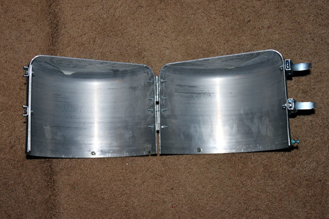
3 1/8 inch coax switch cover modification

Now, when access is needed to either the motor or clutch, the cover can be opened up and removed.  Unless the actual RF contact fingers burn out, there should be no need physically remove the switch for servicing.
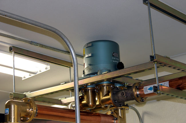
3 1/8 inch coax switch cover, modified

Cover replaced.  This will not have to be removed very often, in fact, I have known some coax switches that never need service.  Still, having the ability to quickly get the cover off and do some basic repairs is a good thing.

Good bye UHF RPU, we hardly knew you

As more and more things that use radio are invented, it is inevitable that the limited spectrum will be squeezed. We see this with BPL, which admittedly causes interference on the HF spectrum, however, proponents have deep pockets. Then there are the so-called “whitespaces” between active TV channels coveted by broadband providers.  Not even the once-sacred GPS system is immune to interference by other radio systems being implemented by companies who “bought” the radio spectrum in question. Although it is quite beyond me exactly how one can buy or sell radio spectrum. I suppose next they will be selling sunlight and rain.

The next chunk of the RF spectrum being repurposed is in the 451-457 MHz range.  This has already been eyed by the Department of Homeland Security for on-scene data communications networking.  However, the latest interested party is the Alfred Mann Foundation, which builds bonic implants.  In an interesting twist, one of the plans for the spectrum in question is something called the MMNS (medical micropower network systems).  This network would be used to transmit commands from the patient’s spinal cord to prosthetic devices.

Many TV stations use 450-455 MHz band for IFB and cueing.  Radio stations use that same spectrum for remote broadcast and telemetry return links from transmitter sites.  RPU frequencies used to be very congested, as remote broadcasts were often an additional revenue stream for radio stations.  These days, most stations to “cellphone” remotes, e.g. the disk jockey goes out to a store or event and calls it in on his or her cellphone.  Some of the more fancy stations use POTS codecs like the Comrex blue box or matrix and very few still use ISDN.  So the first question is how many broadcasters still use UHF (or even VHF) RPU gear (AKA The Marti)?

The second question is what type of damage or reaction could occur if a UHF RPU interfered with one of these MMNS devices?  Some RPUs use fairly high power levels and directional antennas.  But, according to FCC Report and Order on ET Docket 09-36, it is a done deal:

The rules we adopt will allow these new types of MedRadio devices to access 24 megahertz of spectrum in the
413-419 MHz, 426-432 MHz, 438-444 MHz, and 451-457 MHz bands on a secondary basis.

It goes on to say:

Each year, millions of Americans, including injured U.S. soldiers, suffer from spinal cord injuries, traumatic brain injuries, strokes, and various neuromusculoskeletal disorders. The devices that we anticipate will operate under our new rules are designed to provide artificial nervous system functions for these patients.

Which is nice.  I suppose if someone is at the mall setting up the Marti for a remote and when it gets turned on, Grandpa starts break dancing, one should find another frequency.  Do you think the DJs or promotions people remember that?  No, me neither.

If this keeps up, eventually everything is going to interfere with everything else and nothing will work.

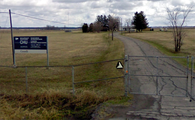
CHU: Time nor tide waits for no man

CHU is an HF time signal station operated by the National Research Council of Canada. It operates 24/7 and announces the hour and minute each minute of every day on frequencies 3,330, 7,850, and 14,670 KHz. This is the Canadian counterpart to WWV and WWVH.  In the strictest sense of the term, it is a broadcasting station, although many would also classify it as an HF utility station as well.  Many countries had HF time signal radio stations at one time, but there are fewer now.  Back in the day before GPS, these time signals were critically important to anyone needing coordinated event timing.  We used the carrier frequency from WWVH as our frequency standard for test equipment.  WWV and WWVH also transmitted a very accurate 1 kHz tone for the same purpose.   According to the CHU website:

Normally CHU’s emission times are accurate to 10-4 s, with carrier frequency accuracy of 5×10-12, compared to NRC’s primary clocks, which are usually within 10 microseconds and 1×10-13 compared to UTC.

Additionally, every minute between 31 and 39 seconds, CHU broadcasts FSK time code with a Bell 103 standard (2225 Hz mark, 2025 Hz space) at 300 bits/second (IRIG time code).  This could be used as a backup for GPS time clocks on automation systems if GPS were to fail for some reason. One would have to write a little software program to decode the hex output and reset the computer clock once per minute accordingly.  That should not be too hard.  LINUX information and software can be found here.  More on CHU time code here.

CHU Ottawa, Ontario, Canada

In my location 3,330 KHz is audible 24/7.  That signal is transmitted with a carrier power of 3 KW into a non-directional vertical dipole antenna as is 14,670 KHz.  The 7,850 KHz signal is transmitted with a carrier power of 10 KW into the same type of antenna.

Canadian Time Signal station CHU, aerial view

There is some discussion of adding an additional time station transmitter in western Canada and of changing the modulation from AM to DRM or at least adding some type of DRM service.

The 80 Amp Circuit Breaker

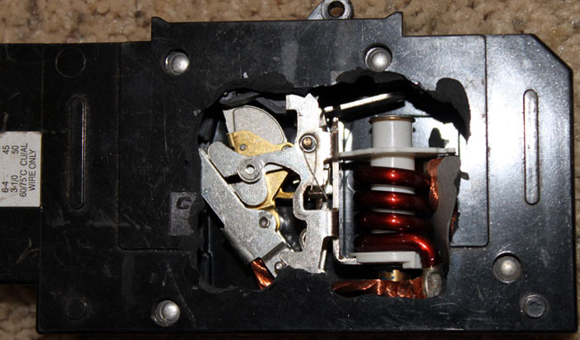
Just because I can, here are a few pictures of the inside of a rather expensive 80-amp DC-rated circuit breaker:

80 amp DC rated circuit breaker open

What is the difference between a DC-rated breaker and an AC-rated breaker? Good question. Because DC is, well DC, the current is continuous. Once an arc is struck, greater separation is needed between conductors to extinguish the arc.  Using an AC breaker in a DC application can lead to an internal arc and fire.  That would be a bad outcome.

Just how did the insides get exposed, one might ask? Well, there I was working on a solar installation with said breaker placed on a horizontal surface waiting for installation when somehow it was knocked to the floor, creating a large crack in the side of it.  Angry I was because this thing set me back some fifty dollars.

80 amp DC rated circuit breaker closed

This picture shows the breaker closed, the contacts are still undercover to the left of the exposed parts. What is cool is one can get a good idea of how a circuit breaker works.  As the current flow increases, the magnetic field around the coil increases.  When it reaches the trip point the small steel piece is pulled down, causing the mechanical assembly to unlock and open the contacts.

Old tech stuff that is taken for granted probably has saved millions of lives since electrical use became widespread.