This was in the Wheatstone newsletter a few months ago. NPR has an interesting test to see if one can hear the difference between various quality .mp3 and .wav files. There are six cuts with three versions each; a 128 kbps .mp3, a 256 kbps .mp3, and a .wav file in no particular order.
I listened to all of them and found the 128 kbps .mp3 was pretty easy to pick out. On the newer material, it was sometimes difficult to tell the difference between the .wav file and the 256 kbps .mp3. Keep in mind that most radio stations stream at 64-128 kbps. Online music services like Pandora (64 kbps for free listeners, 192 kbps for subscribers), Spotify (96-160 kbps for free listeners, 320 kbps for subscribers), and Apple (256 kbps for everybody) offer slightly better quality, especially for paid subscribers.
It is too bad one cannot simulate 15 IPS analog tape. I would bet that a well-mastered recording on analog tape would stand out above anything even remotely compressed.
On the subject of project management; oftentimes, we need to keep track of the small details that can derail a project, blow the budget, and upset schedules. A quick checklist can help to identify things that might not have been planned for. I developed a checklist mentality in the military. There, we had checklists for everything. Simple day-to-day things like disposing of garbage over the side, or pumping the CHT (sewage) tank to complex evolutions like entering or leaving port all had a checklist. On the aforementioned CHT tank; the Coast Guard cutter I was on had a vacuum flush system to conserve water. Emptying the CHT tank involved a complex set of valve openings and closings to route compressed air into the vacuum tank and literally blow the sewage overboard. Anyone can see the danger in such a design. Failure to follow the exact procedure resulted in raw sewage blowing out of the nearest toilets, which were unfortunately (or perhaps humorously) in the lower-level officer’s staterooms.
But I digress.
I have made a series of outlines for different project types. These can be used as general guidelines for project planning and management. Of course, each project is different, but these are flexible enough that they can be adapted on a project-by-project basis.
If you are the type of person that drives around to transmitter sites and steals things; fuck you. You have no idea the problems you are causing to get a few extra dollars worth of scrap copper.
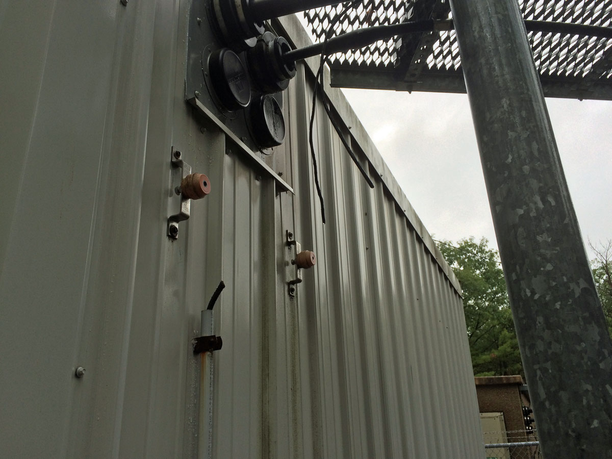
Missing copper ground buss bar
I have a feeling that most of these copper thefts can be attributed to out-of-town tower contractors removing old cellular equipment from towers. Notice, only the buss bar and copper ground wire is missing. They did not try to cut the transmission lines. In other words, they seemed to know what they were doing. I have noticed around here that when a particular contractor, employed by an unnamed large company that rhymes with glint, would work at a site, things would be missing afterward.
Perhaps it is just a coincidence. I have never been able to catch anyone pinching things. However, if this is you, and I catch you, you can rest assured that I will block you in with my car, then walk down the road and call the police.
I have put off writing anything about this for several reasons. First of all, there is a lot of secrecy surrounding the use of the Voltair magic machine. No one will admit to it, however, I have had several off-the-record conversations with various engineers. All of this is hush-hush, unofficially off the record and on the QT, so no names, call letters, or cities of license can be disclosed.
The general gist of these conversations is this; the Voltair seems to be increasing ratings in some cases but not others. It is sometimes too early to tell whether the increased ratings are a one-time anomaly or something more permanent. In one case, an AC station saw 30% increase in numbers, while a certain talk station saw next to nothing. Results are mixed.
In the credit where credit is due department; the Telos Marketing campaign has been effective. Again, from a variety of different sources; Program Directors, Market Managers, and Sales Managers are “beside themselves,” or “giddy” when the UPS truck delivers the Voltair to the front door. In one case, requiring that “I (the market engineer) drop everything” to get it installed as quickly as possible and “acting like it is God’s gift to radio.” It looks like all those trade publication ads are paying off, $15,000 at a time.
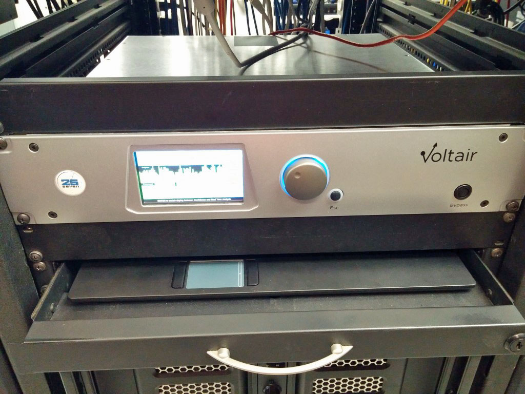
Voltair PPM encoder enhancing device, in the wild
One interesting thing about the Voltair, you can program simulated listening environments such as sporting events, restaurants, kitchens, vehicles, etc. This allows the user to see how their program material is being decoded by a PPM survey device in those types of environments. For example, if you are a sports station, having your program material decode well at sporting events or restaurants and bars might be important.
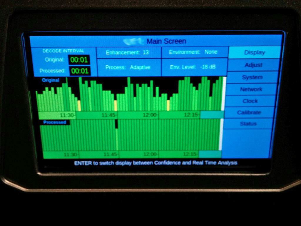
Of course, we have all seen the confidence display:
Voltair PPM encoder enhancer “confidence display”
So, what does this mean? Perhaps there is an inherent flaw in the Nielsen PPM encoding technology. In the past, PPM has been blamed for the demise of the Smooth Jazz format. I always had the notion that Smooth Jazz was responsible for the demise of the Smooth Jazz format. However, if PPM is indeed causing certain program material to disappear from the airwaves, then it would be a case of the tail wagging the dog. If PPM requires that station owners purchase a $15,000 in order to get credit for their TSL and cume, then there is a pretty big problem with the technical aspects of the system.
Of course, there are others that say there is no “Voltair effect.” The Voltair machine is simply a fancy and expensive gizmo that looks good but does not really do anything.
Nielson Audio is having a Webinar on July 21 to address some of the questions regarding the Voltair and PPM encoding for subscribers only. It will be interesting to see what the outcome is.