For all you southerners and west coast people, we have been having an average winter here in the Northeast. While many of our transmitter sites are drive-ups, we have several located at ski area mountain peaks. Technically, those mountain-top transmitter sites are a fantastic way to get the Height Above Average Terrain (HAAT) way up there. Logistically, they are much more difficult to deal with. Installing a new transmitter or even refueling a generator takes major effort. Working in the cold and wind is much more fatiguing and requires paying special attention to protective clothing, hydration, exposure, etc.
Here are a few pictures from Killington and Pico mountain ski areas in Vermont
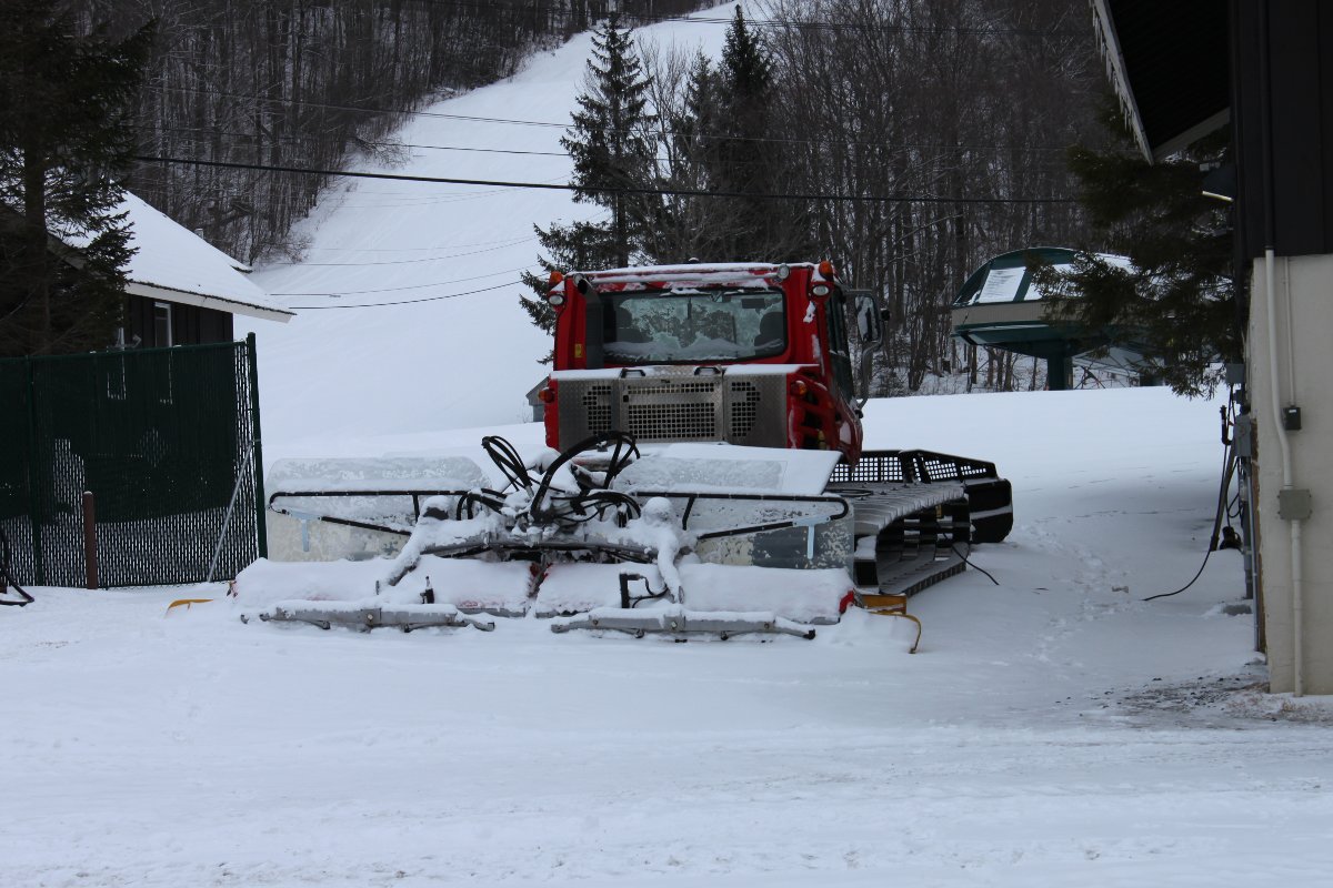
Your ride is here.
The snow grooming machine is the only way to bring anything up to the top of the mountain during the wintertime. In this case, I needed to replace a BW Broadcast TX 1500-watt transmitter.
Trail from ski lift to tower
Even with the snow grooming machine, the last few hundred yards need to be walked. Fortunately, the snow is packed and not too deep here.
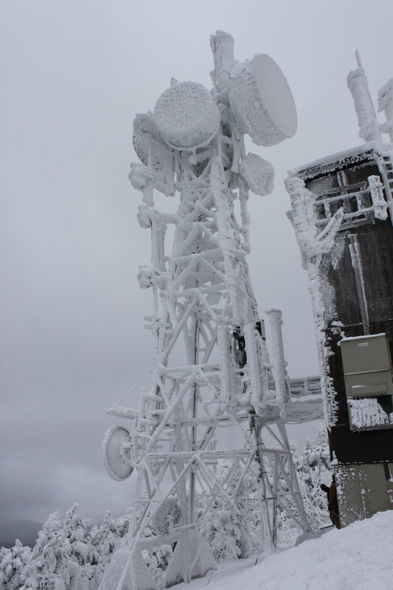
Tower on Pico Mountain
Tower is encrusted with ice. I can tell the tower climber is having a great day:
Tower climber working on ice-encrusted tower
Riding the chair lift back down the mountain gets plenty of strange looks from those skiers coming up:
Pico chair lift
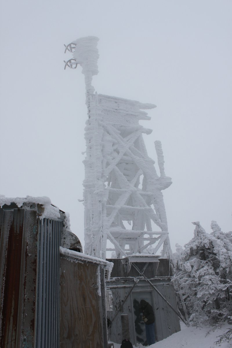
Over on Killington Peak, conditions are actually worse.
Killington Peak tower
The ERI antenna heaters cannot keep up with the ice buildup.
ERI two-bay antenna with ice.
The general manager insists that this winter is not too bad and everything should be working right. My statement to her: Based on my 27 years of experience, your shit is fucked up. But if you know how to fix this, come on up and show me. She deferred.
FM transmitter building and antenna
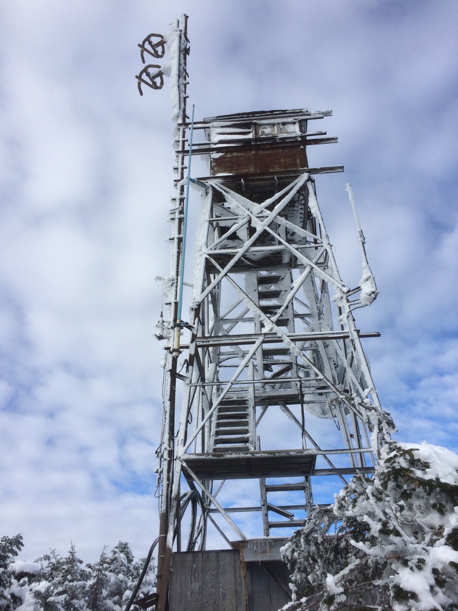
What the fire tower looked like last winter.
Killington peak fire towerTrain from the Gondola to the tower
Shipping container transmitter site from the early 1990’s.
I do not particularly like these. I know, they are relatively inexpensive, easy to come by, easy to install, etc. However, a shipping container was not designed to house a transmitter, they have certain drawbacks. These are, in no particular order:
Air conditioning. Using a traditional Bard-type equipment shelter HVAC unit requires cutting through a lot of fairly heavy gauge steel. What’s more, the steel walls are uneven, requiring a filler.
They are by necessity, fairly narrow. Arranging racks and transmitters along the length of the unit restricts access to either the front or the back of the equipment. Meeting NEC clearance requirements for electrical panels, transfer switches, and disconnects can pose problems.
They are not very tall. Mounting overhead equipment can be problematic as one does not want to drill through the top of the container. Crosswise unistrut is one solution, but it lowers the overhead considerably.
Electrical work is slightly more dangerous. Doing any kind of electrical work, troubleshooting, repairs, etc is a little more nerve-racking when everywhere around you is a metal surface at ground potential.
They are difficult to insulate against cold and heat.
The door-latching mechanisms bind, wear out or otherwise fail over time.
All of those things being said, I am now rebuilding a transmitter site in one of these shipping containers.
Inside view of shipping container transmitter site
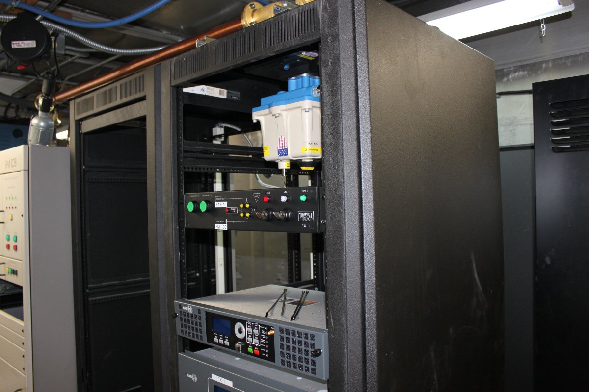
Fortunately, the original electrical work was not bad. The transmitter is a twenty-year-old BE FM10B, which will be retained as a backup. The new transmitter is a Gates Air FAX-10. We have installed several of these Gates Air transmitters in the last two years or so and they seem to be pretty solid units. This is the second 10KW unit I have installed.
Gatesair FAX-10 transmitter in Middle Atlantic Rack
We decided to install the FAX-10 in a Middle Atlantic rack since we did not have a whole bunch of extra room for a separate transmitter rack. The 1 5/8 inch coax switch is installed in the top of the transmitter rack along with a Tunwall TRC-1 switch control unit. The other rack will have the STL and all other ancillary gear. My idea is to have nothing in between the door and the FM10B so it can be easily removed when that day comes. Something, something about planning ahead since it will be likely myself removing the FM10B.
Westwood One, Premiere, Skyview Networks, et al. will be changing their satellite from AMC-8 at 139° W to AMC-18/SES-11 at 105° W longitude. More from AMC8transition.com. There are several considerations for this move:
Dish design and two-degree compliance
Obstacle clearance
Transponder frequencies
Timing
Two degree compliance is going to be an issue for many stations. Those old 2.4 and 2.8 meter mesh dishes are going to have issues with 105º West because that is a very crowed part of the sky. From New York, it looks something like this:
Satellite
Longitude
Inclination
Azimuth
Elevation
Distance
TELSTAR 12 (ORION 2)
109.21° W
0.491°
227.46°
31.09°
38596.91 km
TELSTAR 12 (ORION 2)
109.21° W
0.491°
227.46°
31.09°
38596.91 km
MSAT M1
107.72° W
7.430°
231.14°
38.16°
38011.55 km
ANIK G1
107.33° W
0.013°
225.25°
31.96°
38518.62 km
ANIK F1
107.31° W
0.020°
225.22°
31.95°
38513.76 km
ANIK F1R
107.28° W
0.052°
225.22°
32.02°
38510.37 km
ECHOSTAR 17
107.11° W
0.019°
225.01°
32.08°
38503.29 km
AMC-15
105.07° W
0.025°
222.76°
33.28°
38400.67 km
AMC-18
104.96° W
0.027°
222.64°
33.34°
38400.16 km
GOES 14
104.66° W
0.198°
222.21°
33.38°
38394.57 km
AMSC 1
103.44° W
9.810°
228.37°
43.31°
37616.42 km
SES-3
103.01° W
0.041°
220.41°
34.42°
38307.12 km
SPACEWAY 1
102.90° W
0.032°
220.25°
34.43°
38299.87 km
DIRECTV 10
102.82° W
0.017°
220.17°
34.51°
38292.86 km
DIRECTV 12
102.78° W
0.035°
220.12°
34.50°
38292.93 km
DIRECTV 15
102.71° W
0.009°
220.05°
34.56°
38290.50 km
SKYTERRA 1
101.30° W
3.488°
219.07°
36.33°
38131.32 km
DIRECTV 4S
101.19° W
0.011°
218.24°
35.35°
38228.26 km
DIRECTV 9S
101.15° W
0.014°
218.18°
35.36°
38228.57 km
SES-1
101.00° W
0.016°
218.02°
35.45°
38217.56 km
DIRECTV 8
100.87° W
0.036°
217.88°
35.54°
38211.02 km
Generally speaking, dishes need to be 3.7 meters (12.14 feet) or larger to meet the two-degree compliance specification. For many, this means replacing the current dish. This is especially true for those old 10-foot aluminum mesh dishes that were very popular in the 90s because of the TVRO satellite craze.
If the existing dish is acceptable, then the next issue may be obstacle clearance. Generally speaking, the 105-degree west slot (south of Denver) will be easier to see that the 139-degree west slot (south of Honolulu) for much of the United States. Still, there may be trees, buildings, hills, etc in the way. Site surveys can be made using online tools (dishpointer.com) or smartphone apps (dishalign (iOS) or dishaligner (Android)). I have found that I need to stand in front of the dish to get the best idea of any obstacles. While you are there, spray all the dish-holding hardware with penetrating oil like WD-40, Rostoff, or something similar. Most of these dishes have not moved since they were installed, many years or decades ago.
Transponder frequencies will not be the same, so when the dish is aligned to the new satellite, those frequencies will need to be changed. The network satellite provider will furnish this information when it becomes available. This generally requires navigating around various menu trees in the satellite receiver. Most are fairly intuitive, but it never hurts to be prepared.
The window of opportunity is from February 1, 2017 (first day of AMC-18) until June 30, 2017 (last day of AMC-8). Of course, in the northern parts of the country, it may not be possible to install a new dish in the middle of winter. It may also be very difficult to align an existing dish depending on how bad the winter is. Therefore, the planning process should begin now. A quick site evaluation should include the following:
Network Satellite Receive Location Evaluation
Satellite:
Satellite Location:
Dish is 2°compliant? (Y/N)
Distance to receiver location:
Dish Latitude:
Dish Longitude:
Dish Azimuth (T):
Dish Azimuth (M)
Dish Height AGL:
Dish Elevation:
Observed Obstacles:
(permanent or removable? Owned or not owned?)
Comments:
A .pdf version is available here. Based on that information, a decision can be made on whether or not to keep the old dish or install a new one. We service about 25 studio locations and I am already aware of three in need of dish replacement and two that have obstructive trees which will need to be cut. This work cannot start too soon.
I have been tasked with fixing one of these glorious contraptions. Aside from the usual Energy Onix quirks; design changes not reflected in the schematic diagram and a company that no longer exists, it seems to fairly simple machine. Unfortunately, it has spent its life in less-than-ideal operating conditions.
Energy Onix Pulsar 1000 in the wild. Excuse the potato-quality photo
Upon arrival, it was dead in the water. Found copious mouse droppings, dirt, and other detritus within and without the transmitter. Repaired the broken start/stop switches, fixed the RF drive detector, replaced the power supply capacitors, and now at least the unit runs. The problem now is the power control is unstable. The unit comes up at full power when it is first switched on, then it drops back to 40 watts, then after it warms up more goes to about 400 watts and the audio sounds distorted. This all points towards some type of thermal issue with one of the power control op-amps or another composite device.
After studying the not-always-accurate schematic diagrams, the source of the problem seems to be the carrier-level control circuit. This is based around a Fairchild RC4200AN (U10 on the Audio/PDM driver board) which is an analog multiplier chip. That chip sets the level of the PDM audio output which is fed into the PDM integrator circuit. Of course, that chip is no longer manufactured. I can order one from China on eBay and perhaps that will work out okay. This all brings to mind the life cycle of solid-state components. One problem with the new technology; most solid-state components have a short production life, especially things like multiplier chips. Transmitters are generally expected to last 15-20 years in primary service. Thus, transmitter manufacturers need to use chips that will not become obsolete (good luck with that), or purchase and maintain a large stock of spare parts.
In the meantime, the chip is on its way from China. Truth be told, this fellow would be better off with a new transmitter.