The Nautel AMPFET series transmitters date from the early ’80s through early ’90s. They were Nautel’s first attempt at MF Broadcast transmitters and were quite successful. This particular transmitter was installed in early 1990 at WBEC in Pittsfield, MA:
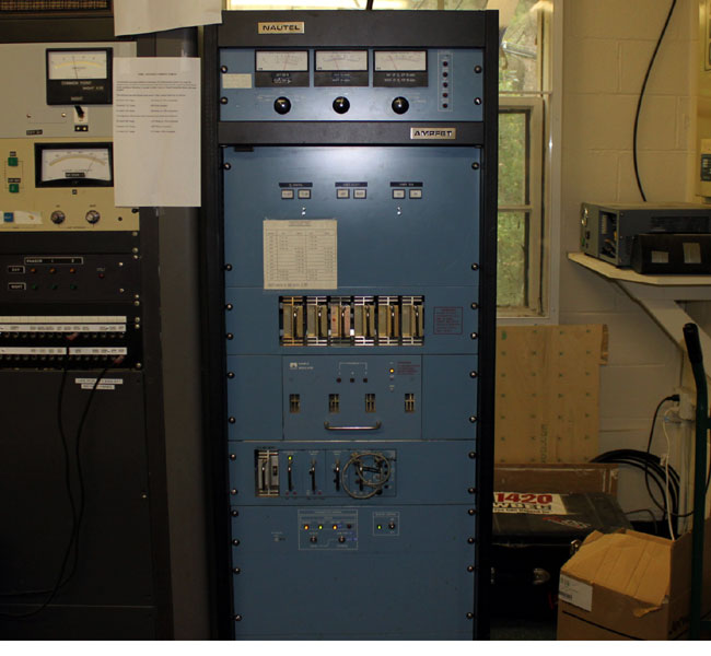
I believe Nautel got started making MW transmitters for Marine Radio stations, Aeronautical and Marine radio beacons, and similar equipment. Their early equipment is very rugged and designed for rough/continuous service. The early solid-state broadcast transmitters like the AMPFET were not hot pluggable but who cares, they almost never break. The design is simple, and efficient and it sounds good on the air.
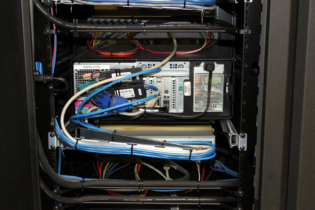
Early transmitters were housed in racks that were much shorter. In later versions, the racks became larger to standardize the transmitter size with comparable units of the day. Inside this cabinet, there is a lot of empty space.
The design is modular, RF modules and power supplies can be removed from the transmitter for repair, unlike the Harris AM transmitter products of the same or later periods.
There later AM transmitter versions built on the AMPFET experience.