I have been finishing up a project which required detuning a new monopole installed near an AM tower. One requirement was a series of field strength measurements along six evenly spaced radials around the AM tower. The point is to see if there is any effect in the omni-directional AM signal (there should not be).
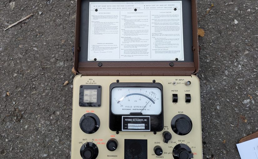
For this, I used the venerable Potomac Instruments FIM-41. As I recall, these units are rather pricey. The frequency range is 0.5 to 5.0 MHz. The basic measurement unit is a Volt/Meter, which is an electric field measurement. Something that measures 1 V/M means that the electric potential between two objects 1 meter apart is 1 volt. The meter will also make measurements in dBm, which is a logarithmic electromagnetic field strength measurement.
Before making any measurements, it is a good idea to check the batteries. Also, the hinged lid part is a loop antenna and there are several contact fingers which can get a little dirty which may effect the measurement accuracy. These should be cleaned off with some alcohol and a q-tip. I have also seen a pencil eraser used.
The directions for meter calibration are on the inside of the lid. Even though I have done this type of measurement a thousand times, I always do a quick read through the directions just to make sure I don’t skip any of the steps. Depending on the power of the signal being measured, I like to calibrate the meter at least a mile or so away from the AM antenna system.
- Check the battery with the function switch in the Batt position. The meter should read within the Batt range
- Tune the signal with the function switch in the FI-Cal-Tune position. This should be done at some distance away from the antenna system. Tune for maximum meter reading.
- Rotate the FIM until the signal is below 10 mV/M, switch the full scale switch to CAL and adjust the CAL OSC for maximum meter reading.
- Switch the Function switch to CAL NULL and adjust the GAIN control to minimum meter reading.
To take readings put the function switch in CAL TUNE and the Full Scale switch at whichever position results in an on scale reading. On less one of the knobs gets bumped, the meter only needs to be calibrated once.
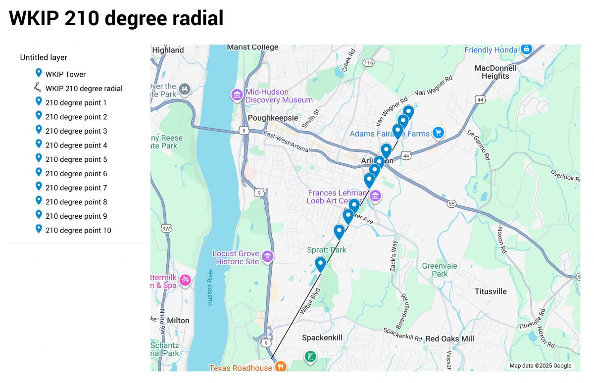
Measurements should be made three or more hours after local sunrise and three or more hours before local sunset. This is to prevent other sky wave signals from interfering with the measurements. The first measurement should be greater than five times the tower height, in this case more than 240 meters.
I used Google Maps to generate a set of points along each radial then noted the coordinates and a brief description on a spread sheet. Since everything was on Google Maps, it was easy to navigate from one point to the next:
Field strength readings follow the inverse square law. Whatever the increase in the distance factor from the radiator, the electrical field will decrease inversely by the square of that factor. Thus, if the distance increases by 3, the field will decrease by a factor of 9.
This can be seen in a field strength vs distance graph which I plotted on an Excel spreadsheet:
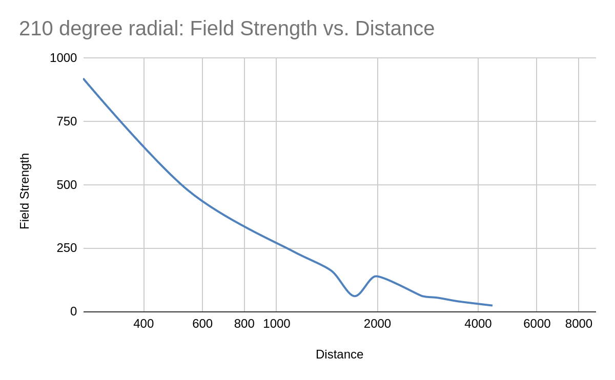
You can see around 2 KM away, there is something re-radiating the signal. This was near a college campus with lots of vertical metal structures around. There are two readings which should probably be thrown out to smooth out the curve.
At one point, further out along this radial, my car was attacked by a Rottweiler. The dog owner just stood in his front yard and watched it happen. After he got the dog back under control, I rolled my window down and told him what I thought of his dog. It is for this reason, I have a dash camera in my work vehicles. Too many times things happen while driving.
Repeat this five more times and call it a day!


Tell us more- for those of us who work in broadcasting but not with AM transmission systems, I will assume that these readings with the FIM-41 were done before the monopole was constructed, in order to get a “before” snapshot of the strength/coverage, with readings done a second time after the monopole is constructed.
And what will need to be done to the monopole to detune it?
Great post as always, Paul. I remember performing monthly checks of the two tower directional I used to engineer back in the 80s. While I’ve used my FIM-41 when a group of us lit up a local AM under an STA last year, the last “fun” project I used it for was when I performed a performance analysis of some Part 15 AM transmitters installed in a 100-percent FCC Part 15.219(b) compliant manner, called the AM Transmitter Challenge.
Reminder to everyone to avoid an unexpected surprise, please remember to remove the batteries from your AM and FM FIMs when not in use.
valvashon: a few years back TPR intentionally “downgraded” WPVD 1290AM from a four tower DA2 at 10kW day/night, to a one-tower omni at 0.4kW day/ 0.016kW night. Afterwards the FCC informed me I had to make a choice: either do a partial proof first, then detune the three unused towers, and run *another* partial proof…..or drop the three unused towers.
I ran the numbers and quickly realized it would be truly heinous pain in the ass to get to about 25-30 of the 60-odd points the FCC would’ve required for the “partial” proofs. Many of them were either *miles* deep into forests, usually on private land, or were in highly urban areas where it’s exceedingly difficult to be far enough away from overhead power lines (on telephone poles) to get a clean reading. A handful of those points were in neighborhoods where I, uh, probably wouldn’t be terribly welcome…shall we say? Several would’ve been in Narragansett Bay or other water, too.
Instead, I found a guy willing to drop, hack up, and remove the three towers in exchange for the Nautel XL12 and Harris DX10 transmitters I had left over from the downgrading. I know it seems like an insane trade, but by that point I’d be trying to sell them for over 8 months and NOBODY wanted them at ANY price. (eek!)
To say Paul deserves some mad props for doing this is a wild understatement. 🙂
Being in this business and meeting a lot of engineers over the years, I’ve heard some truly horrible stories about the monitor points for AMs. In ghettos, sketchy neighborhoods, middle of cow pastures (with cows!) , etc. I don’t have any AM DAs in my roster, so I haven’t had to do that yet. But the stories are something to hear.
Valvashon; Ordinarily, you are correct, before and after measurements would be made on a project such as this. However, this was formerly a directional station, the monopole is located approximately where the second tower was previously. Thus, we didn’t have a clear “before” situation. After all of the readings were done and plotted on a polar plot, the pattern looks omni-directional.
Bill; Removing batteries is a good idea for all equipment that does not get regularly used. I have spend many hours cleaning white/blue crud out of battery compartments…
Aaron; Thank You! Given the advances in technology, it seems the FCC could find a much better way to do these directional antenna systems. One of the huge expenses for AM station owners are antenna systems and the amount of engineering labor they require.
Mike; Always happy to share stories. Hey, we need to get lunch sometime…
Sadly, the partial (or even a full) proof is, sad to say, the best way to do it. Mostly because the soil conductivity maps of the USA used to AM contour plotting? They are not terribly precise and, in a lot of cases, aren’t terribly accurate. The savvy AM DA owner can often go out with an FIM and do a proof, find the soil conductivity isn’t as good in reality as it is on paper, and re-file with the FCC to get considerably more power.
Have to dig out the 1983 KBOI 50 kw DA proof.
4-towers 16 radials. 6 MPs (down to 5 later).
About 40 measurements per radial out to 20 miles.
Pair of freshly calibrated Nems-Clark/RCA FIMs.
We did the majority of 1/10 mile out to 2 miles on foot.
Car & helicopter for the rest. (Landing to take a reading).
I’ll relate the story about the “attempted Prison break” by helicopter later.