The World Turned Upside Down

I have been watching the events unfold in Japan.  It is truly astounding the power of Mother Nature.  While several US networks seem to be tempering their coverage of the nuclear fuel melt, and yes, there are multiple reactor fuel melts in progress, other sources are forthright.  The BBC seems to be on top of things, as well as Russia Today.

Thus far:

  1. No fewer than four hydrogen explosions have taken place in all four reactors at the Fukushima-1 Power plant.  The after the third explosion yesterday in unit 2, there are two major concerns; breach of the reactor vessel(s) and runaway nuclear fission.  After that explosion, the pressure in the unit 2 reactor suppression chamber dropped from three atmospheres to one atmosphere, indicating the suppression ring had breached.  Currently, the nuclear disaster is categorized as a 6/7, surpassing Three Mile Island.  The worst case scenario:  Reactor Unit #2 completely breaches, this unit contains Mox fuel Note: unit #3 contains the Mox fuel. (mixed plutonium/uranium oxide), which is far more dangerous than the fuels in the other reactor vessels.  Mox fuel has a lower melting point and could potentially melt into a pool at the bottom of the reactor vessel resuming fission.  Criticality?  Yes, but not the high-order type as seen in a nuclear weapon.
  2. The root cause of the disaster is the loss of cooling after the reactors were shut down.  The nuclear fuel cores require cooling for at least two to four weeks after shutdown.  The backup diesel generators went offline approximately one hour after the units were automatically shut down during the earthquake.  Three probable causes for this have been proposed;  the electrical switch gear for the generators was in the basement of the generator building, which was flooded by the tsunami, fuel contamination/fuel loss, and submergence of the GENSETs by seawater.  All three of these scenarios point to a design flaw.
  3. Radiation levels have varied but are elevated, peaking at various times before and after each explosion.  Until this morning, the major radiation plumes were being blown offshore.  The wind has become variable, causing the downwind zones to shift.
  4. Prevailing east winds could blow some of the contamination to the west coast of the US within 36-48 hours, the east coast by 48-72 hours, and in 7-10 days there will likely be a band of radioactive particles in the jet stream that circles the globe in the northern high latitudes.

Good explanations: MIT NSE Nuclear Information Hub

I never thought I’d recommend a Russian News media source, but they seem to be nailing it.  There is also some coverage on NHK shortwave frequencies:

All times UTC / target areas: af (Africa) as (Asia) EU (Europe) na (North America) pa (Pacific)

0500-0530: 5, 975 KHz (eu) 6,110 KHz (na) 9,770 KHz (af) 15,205 KHz (as) 17,810 KHz (as)
1000-1030: 9,605 KHz (as) 9,625 KHz (pa) 9,840 KHz (pa) 11,780  KHz (as)
1200-1230: 6,120 KHz (na) 9,625 KHz (pa) 9,790 KHz (eu)
1200-1300: 9,695 KHz (as)
1300-1330: 9,875 KHz (as)
1400-1430: 5,955 KHz (as) 9,875 KHz (as) 21,560 KHz (af)

But not to worry, everything is okay.  There will be no detrimental effects of this, whatsoever.

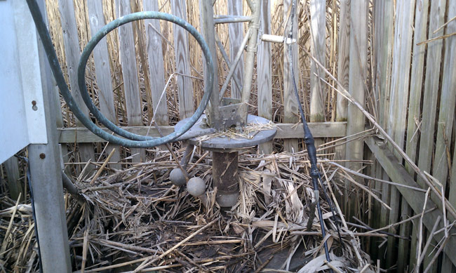
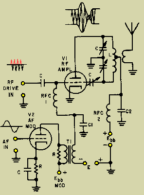
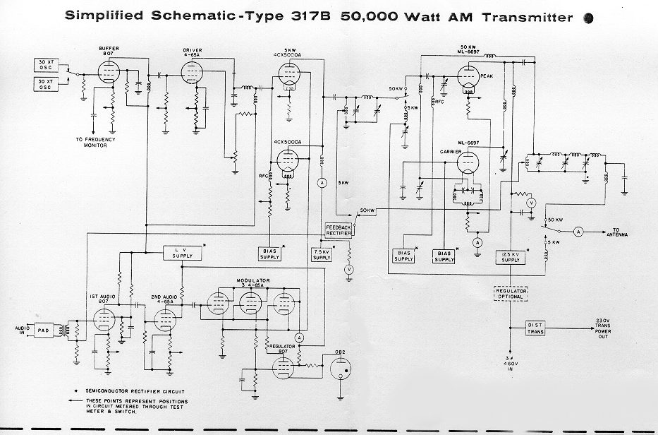
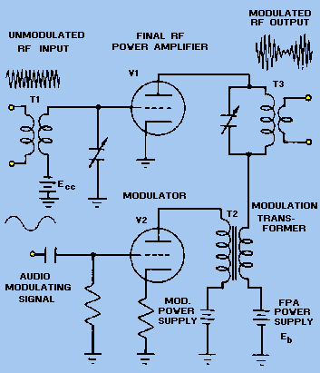
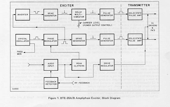
Regardless, I have headed down to the basement and dug up my CD V-700 RAD meter.  I salvaged this from the dumpster at WPTR after one of the contract engineers threw it away in the early 1990’s.  I believe I used this meter to measure the radiation from the tubes in the BT-25A and the MW50B transmitters.

According to the “Operational Check Source” on the side of the meter, it still works and is pretty close to the calibration level.  Even if it is not totally accurate, it will still indicate an increase in radiation.

Anton Model 6 CD V-700 radiation meter

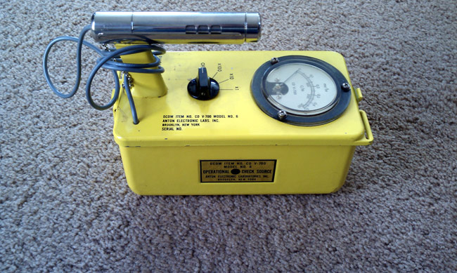
This is an Anton Model 6, which is the most sensitive of the V-700 series meters.  It can be used to check background radiation levels and/or contamination of food or clothing.  The best plan is not to ingest radioactive particles in food and water.  Why wonder about it, when you can know?

Broadband for First Responders Act of 2011

I found this bit of proposed legislation by Peter King (R-NY) interesting:

Not later than 10 years after the date of enactment of this Act, the paired electromagnetic spectrum bands of 420–440 megahertz and 450–470 megahertz recovered as a result of the report and order required under subsection (c) shall be auctioned off by the Federal Communications Commission through a system of competitive bidding meeting the requirements of section 309 of the Communications Act of 1934.

Will this mean broadcasters be losing their Part 74 Broadcast Auxiliary RPU licenses?  Section 74.402(4)(b)(4) lists those frequencies as 450.03125 through 450.950 and 455.03125 through 455.950 MHz in various channel configurations.  These frequencies are used mostly for RPU but are also used for TSL systems. This is the NITA frequency allocation chart.  The RPU frequencies are shared but I doubt an entity that has paid through the nose for exclusive use of a frequency band would be interested in that. Further, according to Part 97.301(a), the 70 cm Amateur Radio frequencies are from 420 to 450 MHz.  That has the Amateur Radio users quite upset, and rightly so.  I don’t know if this has filtered down to broadcasters yet, but losing RPU and TSL frequencies would likely be an inconvenience, to say the least.

What gives?  Reading through the bill, it seems there would be a multi-part shuffle over several years to move the “first responders” to a nationwide system on the 758-768 and 788-798 MHz frequencies.  The then “empty” frequencies would be auctioned off, except some of them aren’t so empty.

Does this mean that all the existing police, fire, and ambulance radios will be phased out in favor of the 700 MHz units?  Didn’t they just install a bunch of trunked 800 MHz systems recently? Wasn’t that an expensive boondoggle that still has yet to be sorted out in some locations?  Ah well, it’s only $2 billion or so taxpayers dollars, which, to fight terrorism, anything goes.

Creek floods AM tower array

We have received somewhere between 5-6 inches of rain in the last four days. That, coupled with the deep snowpack and the still-frozen ground has led to some flooding. The WLNA antenna array is located along the Peekskill Hollow Creek in northern Westchester County, NY.  Back in 1980, it might have seemed like a good idea to locate an AM station in a tidal swamp along the Hudson River.  I am sure the land was not that expensive and from an engineering standpoint, having a continually wet, partially brackish ground system may have seemed like a slam dunk.

Unfortunately, the idea never really panned out in the application.  First of all, the neighbors had other ideas, fighting the radio station owners all the way to the NY State Supreme Court.  Secondly, technically, it never lived up to expectations.  The original non-directional antenna on 1430 was a 1/2 wave tower which by all accounts, worked very well.  It did not, however, allow for nighttime service, which is why the new sight and array were sought.  By the time the system was built, AM was already in steep decline and I doubt the owners ever recouped their investment.

Fast forward to today.  All five base insulators are under water and the transmitter is off the air.  These are pictures from last Wednesday after the first flood waters receded from the Monday/Tuesday storm.  I imagine it looks worse this morning, although I don’t own a boat and won’t be wading out there to look.

Base insulator, tower 2 WLNA array, Peekskill, NY

This is tower two of the daytime antenna array.  Clearly, it spent some time underwater.  We cleaned off all the debris from all the tower bases.  A far worse prospect is the ATU’s:

WLNA tower 1 ATU, Peekskill, NY

This is the Antenna Tuning Unit for tower 1, which is the reference tower for both the day and night arrays.  The E.F. Johnson contactor in the bottom of the cabinet was fully submerged for an undetermined amount of time.  The bottom of the unit is covered in fine silt.  The high water mark is visible on the right side of the aluminum cabinet.

The contactor is going to need to be replaced, or at least rebuilt.  The ATU cabinet will need to be washed out.  There are two other ATUs that suffered the same fate.

WLNA antenna array, towers 4 and 5
WLNA antenna array, towers 3 and 5

This is the end of the catwalk next to the Peekskill Hollow Creek looking west towards the Hudson River.  The water level reached the bottom of the catwalks and had receded about 4 feet when this picture was taken.

WLNA antenna array, tower 5, peekskill, ny
WLNA antenna array, tower 5, Peekskill, NY

Lookup east, upstream at tower 5.

WLNA antenna array looking north, Peekskill, NY

This is the antenna array looking north, with my back facing the creek.  Tower one is the center tower, tower two is on the right and tower four is on the left.  The daytime array consists of towers 1, 2, and 3 bearing 300 degrees.  The night time array consists of towers 1, 4, and 5 bearing 335 degrees, so the array makes a big X in the swamp.  More from the FCC database.

It is going to take a lot of work to clean out all these ATUs and repair the damage.  Clean water is at least 1000 feet away.  My question is; why bother?  Once upon a time, this station was viable, well thought of in the community, etc.  Now, I doubt anyone knows it is off the air.  The current ownership over the last thirteen years did, what I’d like to call, a controlled flight into the ground.  Axing staff, cutting maintenance, and generally neglecting the station.  Why not take it dark for a while and figure out what to do with it?  Likely somebody would buy it, even if for the land it sits on.  Anyway, the grind continues…

Methods for generating Amplitude Modulation

Amplitude Modulation (AKA AM) was the first modulation type to impress audio on an RF carrier.  Prior to this, information was transmitted via on/off keying of a continuous wave transmitter using Morse code or some equivalent.

There are several methods for generating AM in a transmitter.

1. Low-level modulation.  The modulation is developed in the first stage RF section, then amplified by subsequent stages to full power.  Simple and easy to implement, especially for mobile transmitters and SSB installations.  Disadvantages come from the need for linear amplification through all the stages requiring class A or AB amplifiers and do not reproduce wide band AM well.

Grid Modulated AM transmitter

2. Doherty modulation. William Doherty came up with an ingenious way to use a low-level linear modulator with good to excellent efficiency. Under full carrier, no modulation conditions, the carrier tube is generating the RF carrier, and the peak tube is mostly cut off (very little current). When modulation is applied, the peak tube then begins to conduct, the output of this tube is combined with the output of the carrier tube through a 90° LC network, which is the same as a 1/4 wavelength transmission line.  The effect of this is to lower the output impedance, thus allowing the carrier tube to modulate 100 percent.

Later, Continental Electronics and Jim Weldon somewhat modified this system in their 317C series high-power transmitters.

Continental 317B simplified schematic diagram

3. High level or plate modulation.  The RF and Audio sections are developed separately within the transmitter, then combined in the final stage of the transmitter.  Older systems used a modulation transformer.  The advantages are all the amplifiers can be run class C or greater, which reduced electrical consumption and power supply requirements.  Much higher power levels are achievable with this design.  These transmitters also reproduce wide-band audio much better than low-level modulated units.  They are also extremely rugged. Disadvantages are the system requires large audio sections and they take up a greater area and are not as efficient as later modulation methods.

Plate Modulated AM transmitter

4. Ampliphase.  A phase-modulated system developed by RCA where the transmitter developed two RF signals in the final, 135 degrees apart.  To modulate the signal, the phase relationship between the carriers is varied, more toward 180 degrees would be a negative peak, and more toward 90 degrees a positive peak.  These transmitters required less space and were more efficient than traditional plate-modulated transmitters.  They required careful setup and tune-up to reduce distortion and somewhat unfairly earned the name “amplifuzz” from some engineers.

RCA BTE 20 ampliphase AM exciter
RCA BTE 20 ampliphase AM excit

5. PDM or PWM.  This is also a high-level modulation scheme but with some slight variations. The carrier power level and modulation levels are set by a PDM encoder card. In Harris transmitters, the PDM frequency was 75 KHz. The carrier is set by the amplitude of the PDM waveform, and the modulation is determined by the duration of the pulse. PDM transmitters require power supply voltages about twice the voltage of a standard high-level plate-modulated transmitter. They also require a damper diode to conduct the B+ voltage to back to the power supply during negative peaks, otherwise, the PA voltage will attempt to rise to infinity. I have found the damper diode to be the weak link in a tube-type PDM transmitter.

Solid state transmitters also use this design with either MOSFETs or BJT, which are then combined in parallel to generate the required output power.  This is most often called “Class E” or something similar.  In that system, each pair of modulator MOSFETs has its own fast-acting damper diode, usually protected by a fuse.

Harris MWx tube type PDM transmitter

6. Direct Digital Synthesis. This is a patented design from Harris Broadcast used in their DX series transmitters. The incoming audio is sampled at either the carrier frequency or 1/2 the carrier frequency depending on where in the band the station falls. The solid-state PA modules are then switched on and off at the carrier frequency with the audio levels imposed on the carrier information.  The explanation is simple, the application is complex:

Harris DX series AM transmitter block diagram

Of all these transmitters, the Harris DX series is the most efficient from a power input (AC) to power output (RF) perspective.  There are several methods of reducing electrical use by reducing carrier power levels during lulls in modulation.  The Continental 418E and later series transmitters can reduce carriers up to 6 dB using CCM.   Harris and Nautel use similar systems on their DX and XL transmitters respectively.  The wheatstone corporate blog has an article: Greener AM transmission Methods that details others.

As far as simplicity, serviceability, and rugged design, the high-level plate modulated transmitters cannot be beaten.  Many Amateur Radio operators build these units from scratch using old parts, tubes, and other reused equipment readily available, often for free.  I have, in fact, donated several 1 KW AM transmitters to ham radio operators over the years.

If I were to design a “transmitter of last resort,” to use in case everything else fails, it would look something like this:

813 Tube type 250 watt transmitter final
813 Tube type AM transmitter modulator section

The disadvantage of that design is it requires a 2KV power supply, which has its own set of safety concerns.  I might substitute 833s for 813s and use heavier iron in the modulation transformer.  That way the transmitter could develop a 500 to 1,000-watt carrier.  The great thing about tube transmitters is, given the right output components, they can be tuned into almost any load.  They are also easily adaptable for emergency operation into temporary antennas.