Found in a pile of junk in the corner of an older transmitter site, this Gates BFE-50C or otherwise known as an M5675 Amplifier. This was used as an IPA in a Gates FM 1C transmitter installed around 1960 or so. The rest of the transmitter has long since departed, likely to the scrap yard, however, somebody thought to remove this and set it aside.
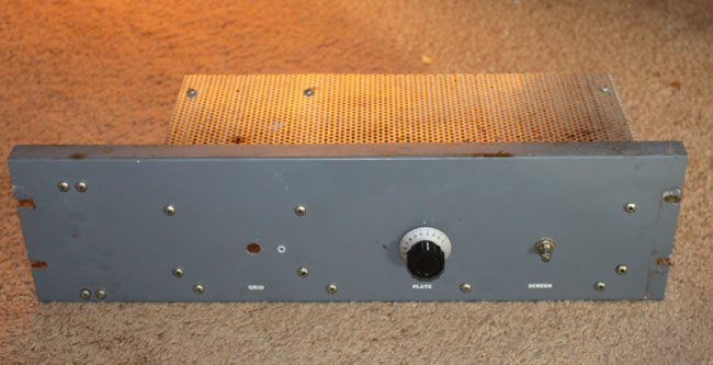
This unit is missing it’s grid tune knob. The grid tune capacitor is still there, however. There is also some evidence of heating on R403 and R407/408 likely due to a prolonged overdrive condition. Otherwise, it is in good shape.
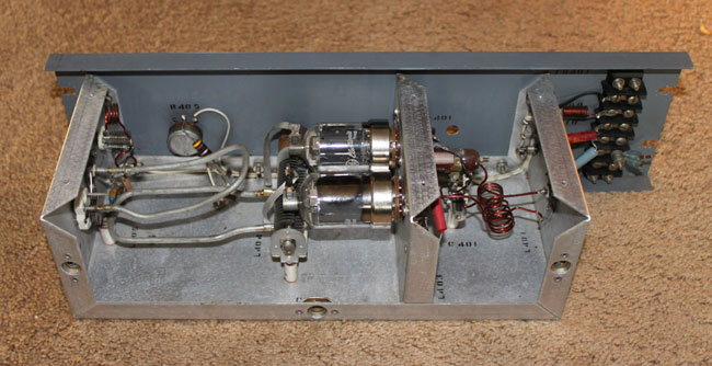
The design is pretty simple, a pair of 6146’s in push pull, three watts in nets about 50-60 watts out, according to the manual, which can be found here (.pdf). The power supply voltages are fairly tame, 500 volts plate, 300 volts screen. The one thing that this design does not have is any type of harmonic filtering. When used with a larger transmitter, this makes sense because the transmitter output will have overall harmonic filters. If this was to be used on it’s own for any reason, a good harmonic filter would need to be designed and installed.

The schematic is straight forward. Gates, the old Gates Radio of Parker Gates, designed good equipment. Click on image for higher resolution.
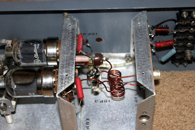
It is a bit hard to see in this picture; the input section consists of three turns of #14 gauge wire coupled to two 4 turn sections of 14 gauge wire on either side of it. This is matched to the grids Screen1 of the 6146s with C401. L412, C411 and L413 form a low pass filter. L412 consist of one turn #14 gauge wire, L413 is five turns of #14 gauge wire. All coils are 3/4 inch in diameter.
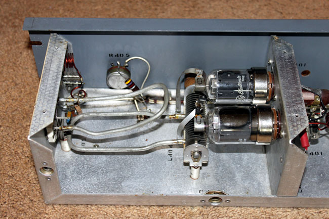
The output section is even simpler, using just one loop of small diameter copper tubing. The plate tuning is accomplished by C407, loading is C406. Power output is adjusted by varying the screen voltage using R405.
Advantages of this design:
- The 6146 tube is fairly rugged, at class AB the 50 to 60 watt output range is well within the plate dissipation for a push pull configuration.
- No special parts are needed, everything can be found or fabricated by hand
- The 500 volt supply is fairly tame, maximum PA current should be less than 0.2 amps for 50 watt output and 50% PA efficiency.
- Output tuning and load allow for tuning into less than ideal loads, if required.
- If operated as a stand-alone unit, some type of plate current meter should be used to aid tuning. A harmonic Filter would need to be designed and built for the output.