Not related to radio engineering, however, I’ve been doing daily radiation measurements at my house (upstate NY) since the Fukushima disaster. A few bits of housekeeping information first: This is a CD V-700 radiation meter, which is a model 6 manufactured by Anton. It was last calibrated in 1986. When I place the Geiger tube over the operational check source, it goes up to about 2 mr/hr as described in the owner’s manual. It may not be completely accurate, but it is accurate enough for this experiment.
This video was taken on March 17, 2011. It sets a good reference for normal background radiation levels:
This video was taken on March 27, 2011. It shows a significant increase in background radiation. Further, much of this appears to be gamma radiation, as the gamma shield is closed during this video:
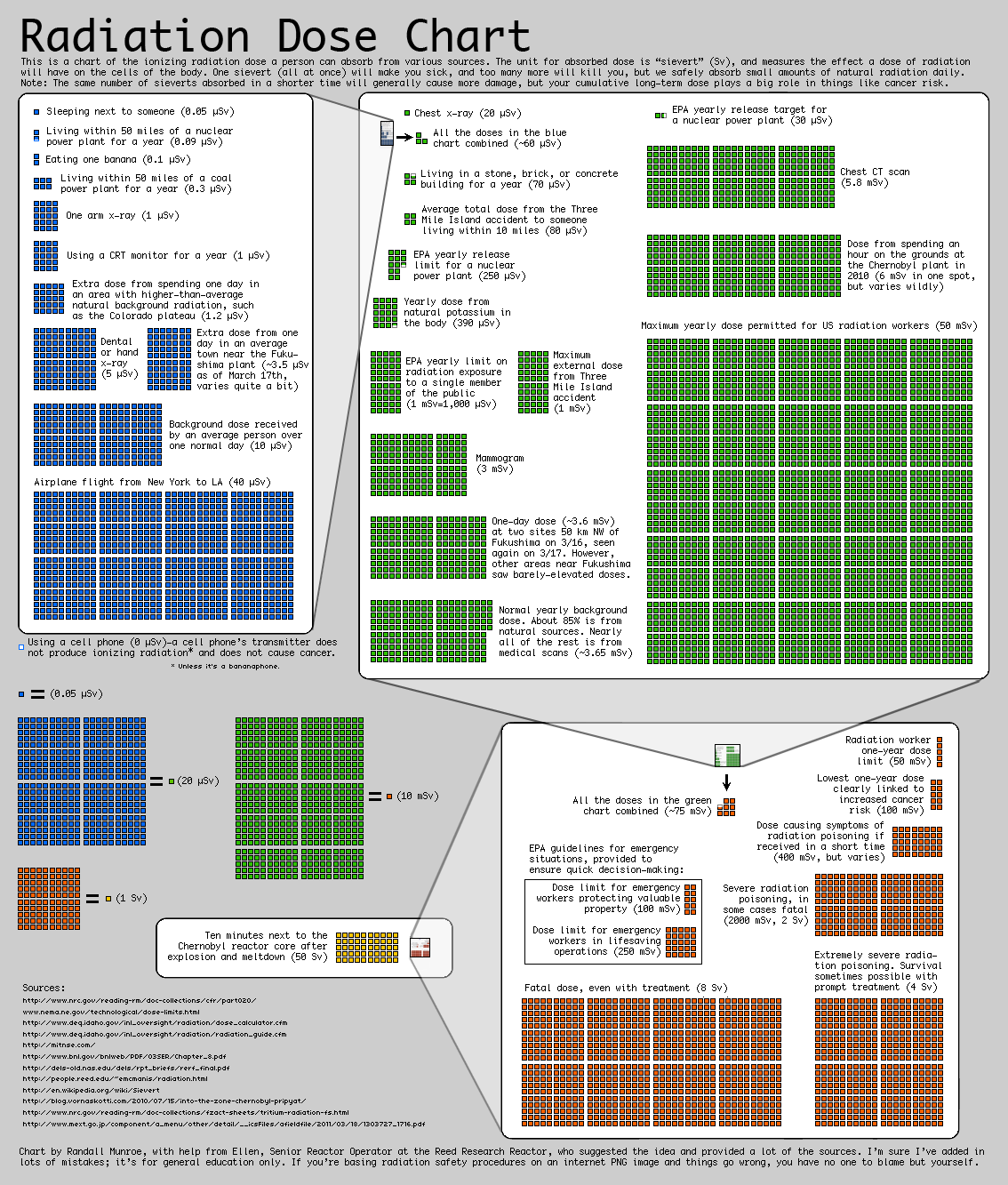
Both of these videos were taken on the most sensitive (x1) setting. It shows that the radiation level is about 8 to 10 times above normal. It is a cause for concern, but not alarm. Not yet. If it continues at this level for several days or weeks, then the overall radiation exposure will begin to accumulate. Right now, it is about the same as taking two NY to Los Angles flights per day, according to this chart (0.35 mr/hr = 3.5 uSv per hour x 24 hours = 84 uSv per day):
Radiation Chart
As of March 28, 2011, the wind has shifted more to the southwest and the levels have dropped somewhat. From our beloved press corps, there have been a few reports here or there on this, most with the standard “this is nothing to worry about” disclaimer. I have also noticed a series of stories and reports that radiation is not all that bad, don’t worry about it, living next to a nuclear plant is fun(!), and we don’t know as much about radiation as we thought we did. I don’t know about all that, I’d rather base my opinion on the scientific body of evidence gathered over the last one hundred years or so. The conclusion of that information is that radiation is bad for human physiology and exposure should be limited.
There is also a crowdsourcing website called “Radiation Network,” which is showing all the levels across the US are normal. This makes me wonder about their instruments and or candor, you can draw your own conclusions.
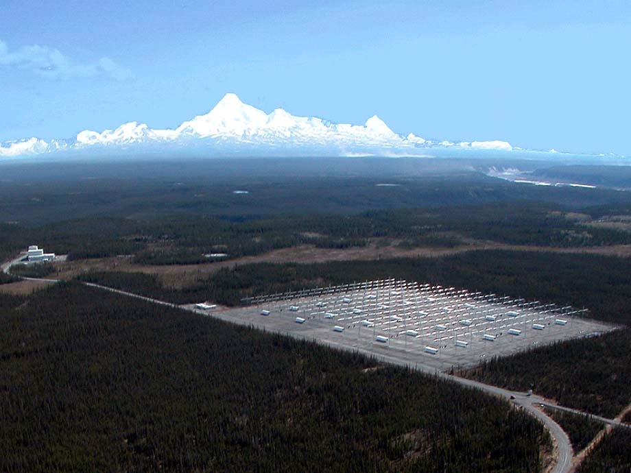
This looks interesting and many people have speculated as to what it does. The High Frequency Active Auroral Research Program, AKA HAARP in the parlance of the acronym heavy US military, is designed to do Ionospheric research.
HAARP antenna array, Gakona, AK. Courtesy HAARP
That array is described as 180 crossed dipoles in a rectangular planar array. The transmitter power output is reported as 3.6 MW with an ERP of 5.1 GW in the frequency range of 2.6-10 MHz. That’s a whole bunch of watts. The array was built around 2004 and operates intermittently at various powers and frequencies.
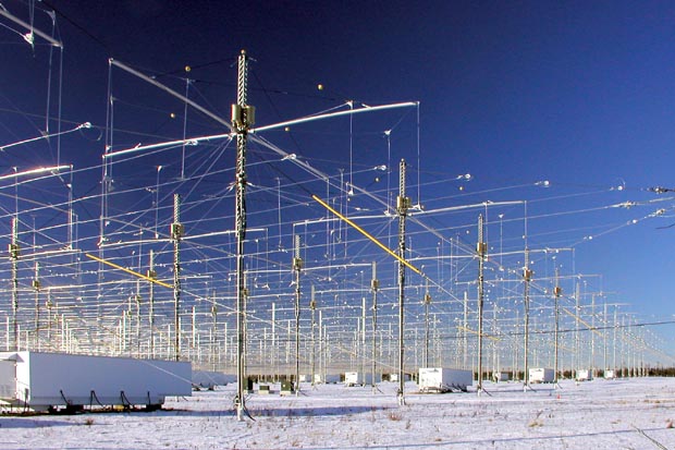
HAARP array close up, Gakona, AK. Courtesy of HAARP
A view of the individual antennas. They look like broadbanded fan dipoles arranged in cross configuration. Depending on how they are phased, the gain of this system would be a factor of 10 or slightly more.
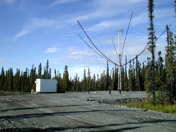
HAARP receiving antenna, Gakona, AK. Courtesy of HAARP
The main focus of this system is to study the Ionosphere, which is a critical part of wireless communications. In the HF frequency range, (and to some extent MF) signals bounce off of the Ionosphere (so called “skip”) and can travel many thousands of miles on relatively low transmitter powers. All satellite based communications pass through the Ionosphere on the way to and back from the satellite, as does GPS. Back in 1990, when the US Navy and Air Force proposed the project, HF radio was a key part of their communications network. Since then, mostly satellite modes have taken over that role, but HF is still relied on heavily. Further, studying the cause and effects of such things as Aurora Borealis, the Van Allen belt, high altitude nuclear burst,VLF, ULF, and other communications phenomena is important not just to the military, but society as a whole. We rely heavily on the communications infrastructure for things like cellphones, broadband internet, telephone service, banking, credit card transactions, etc. It has been long known that disruptions in the ionosphere can impact all of those services.
The problem with the Ionosphere is its location right on the edge of space. Too high for aircraft or weather balloons to reach, too low for satellites, it remains, for the most part, a mystery. The program was founded to research this area by beaming focused energy to small areas and observing the results from a number of different locations.
Of course, the system is not without controversy. It is a big scary looking antenna system in the middle of the woods in the far north. Conspiracy theorists have accused the US of using HAARP as a weather modification scheme. Since it’s construction it has been blamed for:
droughts
floods
hurricanes
thunderstorms
earthquakes
major power outages
TWA flight 800
Gulf war syndrome
Chronic fatigue syndrome
Movement of the magnetic poles
And others. Naturally, none of these things ever happened before the array was constructed in 2004. In another wrinkle, TWA-800 crashed in 1996 off of Long Island, NY. In all fairness to the Conspiracy Theorist, USTPO number 4,686,605 (Eastlund/ATPI) does indeed mention weather modification as a theoretical possibility. While 5.1 GW may seem like a lot of power, I doubt very much that it could compete with the Sun’s output and change weather patterns in any perceptible way.
Everything about this program is top secret, or rather T O P S E C R E T or above. Exactly how it accomplishes these things, no one can say. As with any T O P S E C R E T government program, ample access and pictures are available to the public from a variety of sources and annual open houses that are held.
People generally fear what they don’t understand.
In this respect, the government, through perhaps the sometimes security conscious military, has done itself no favors.
The reality is this: Taking into account free space loss, the distance (100 to 350 KM or 62 to 218 miles) and power levels reportedly being used, the power density is no more than 3 μW/cm2, as given by the HAARP website. My own calculations show: If the ERP is 97.1 dBW or 127.1 dBm, then the free space loss at 100 KM and 2.6 MHz is 80.7 dB, which would be the worst-case scenario and might not be technically possible with those antennas (it would be much larger due to antenna inefficiencies at 2.6 MHz). However, with that configuration, the power density is 0.47 μW/cm2, far below the stated 3 μW/cm2. To put this into proportion, the Sun averages about 7.32 W/cm2 over the entire surface of the Earth. More near the equator, less near the poles. To compare the two; HAARP=3μW/cm2, the Sun=7,320,000μW/cm2. That is not good enough for some because HAARP is located far north, about 62° N latitude, so it gets less sun. Even so, the power from the Sun at 62° N is still many orders of magnitude greater than the HAARP array.
There are plenty of things to be concerned about in this world, this is very low on the list. The conspiracy theorists should do a little more in depth research on their subject matter, it would lend a bit of credibility to their story.
I received this link in the comments of a previous post and found it interesting. The BBC will be closing down 648 KHz, Ordfordness England at the end of March, no doubt due to budget cuts. The site has been in use since 1972. Prior to this, the site was formerly an OTH array, COBRA MIST, which was then adopted for MW broadcasting. The video is 17 minutes long, but, if you are interested in radio history, technical aspects of AM broadcasting, and the like, it is interesting.
These are 600 KW transmitters. As Andy Matheson, transmitter engineer, explains, with a wry smile “I find them (transmitters) very satisfying, I enjoy either day work or shift work, just really working with transmitters has always been very satisfying…” I couldn’t have said it better myself.
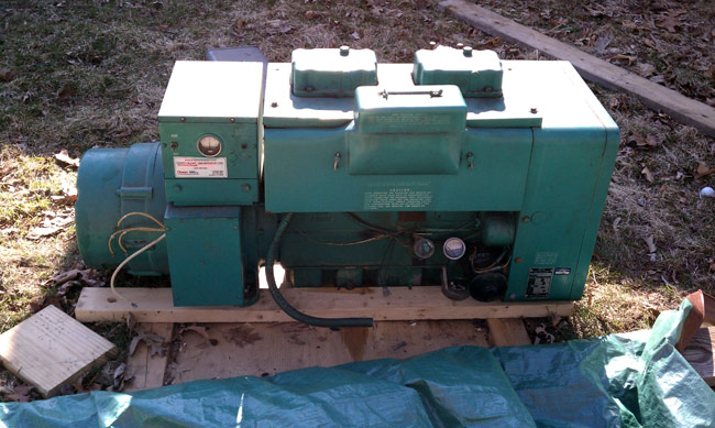
I was fortunate enough to acquire this generator last fall. It was new in 1969 and has unknown hours on it, but it appears in decent shape. I am going to do a level two overhaul and install it as backup power for my house/shop. The first order of business is a complete inspection. I discovered a few problems; the starter didn’t crank, the distributor was loose, and the carburetor had some burned-out chunk of metal attached to it.
Onan 12JC4R generator
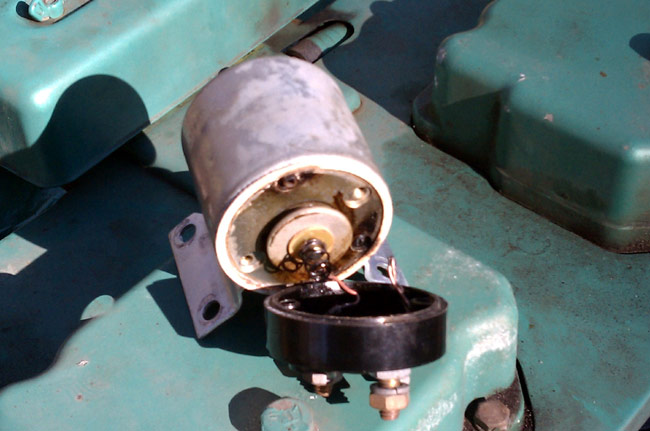
First, the starter: These units use a Prestolite MEO3006 starter, which is common to several Chrysler products from the late ’60s and early ’70s. This is obviously a replacement unit, as it is not “Onan Green.” When I hooked a battery up and tried to turn the motor over, the start relay clicked but nothing else happened. I dismounted the starter and removed the starter solenoid. The interior of the starter motor looked in good condition, which points to the solenoid. Sure enough, I removed the back of that unit and found two wires burned through and a large blackened area. While I had the starter off, I hooked it up to a 12-volt battery and it worked fine. A new starter costs $469.00, and a new solenoid cost $59.00. I opted for the solenoid.
Onan 12JC4R burned out generator starter solenoid
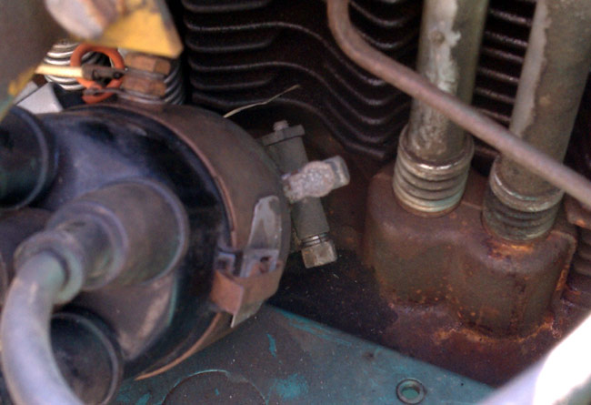
The next thing is the distributor. I was checking the points and contemplating replacing the breaker points with an electronic ignition when I discovered the distributor could turn 1/8 of a turn in each direction, as when making timing adjustments.
Onan 12JC 4R distributor clamp
I used a 3/8 box wrench and tighten up the clamp holding the distributor shaft. It took several turns and makes me wonder why it was loose. I will have to check the timing with a light once I get it running. This also could be why the generator was not running when we took it out of service.
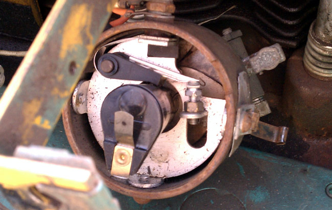
Onan 12JC 4R rotor and breaker points
As for the points, they look brand new, as do the rotor and distributor cap.
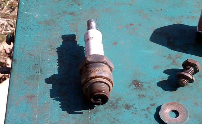
Onan 12JC 4R generator spark plug, champion H8C
The spark plugs look well used and the plug wires look original.
Finally, there was an electric choke mechanism on the carburetor which is completely unnecessary for a propane-fueled unit. The choke plate itself was wired open. The electric choke was burned open, so I removed the assembly. I then spent some time at the local NAPA cross-referencing parts. Here is a tune-up list:
Nomenclature
Onan part (old)
Onan part (new)
Napa Part
Alternate
Oil Filter
122A185
122-0193
1084
Fram PH16
Points*
166P245
166-0245
CS709
Rotor
166P234
166-0234
AL58/AL52
Distributor cap
166B307
166-0235
AL91
Condenser*
166P310
166-0310
AL38
Ignition Coil**
166B310
166-0859-02
701002
PRX 405011
Plug wire #1
167A1410
167-1602
701064
Plug wire 2,3,4
167A1409
167-1602
701063
Spark Plug
167-4
167-
Champ H8C***
Air Filter
140B640
140-1907
7-02241
Starter
191C324
191-0324
Prestolite MEO3006
Solenoid
N/A
191-0433A
ST103
*Electronic ignition set
N/A
166-0825
Pertronics 1545**
**Ignition coil W/PRX 1545
PRX 405011
*Condenser and breaker points can be substituted for an electronic ignition kit, either Onan 166-0825 or Pertronics 1545 with Pertronics PRX 405011 coil. **Pertronics electronic ignition must be used with Pertronics coil ***Champion RH8C plugs should be used with replacement wires without noise suppression plug boots.
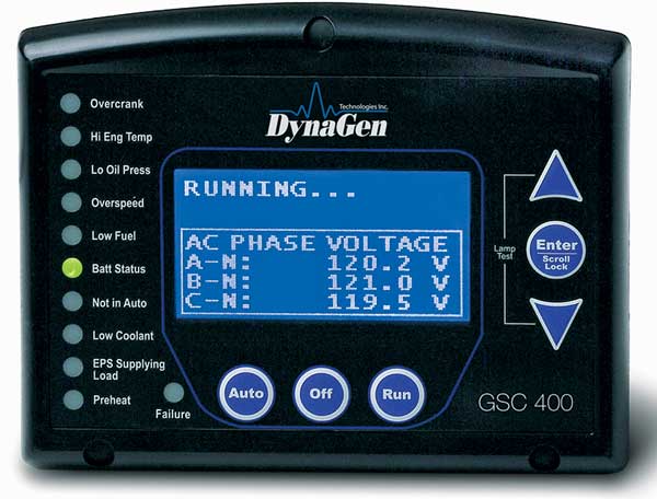
This is for an Onan 12JC generator circa 1969 with a Studebaker engine. Other models/years may vary. The other issue with this unit is there is no supervisory monitoring and control. There is no oil pressure loss, overheating, or over-crank faults. This is why the starter solenoid failed. To remedy that situation, I started to design a better control circuit. Then I looked around on the inner tubes and found somebody had already done this. DynaGen makes the GSC400p which can monitor oil pressure, engine temperature, frequency, engine RPM, hours, voltage, and current. It can fault for any out-of-tolerance condition, as programmed by the user.
Retrofit generator controller
I plan to install this in the original control box, leaving the original control circuit intact by using the remote start/stop connections. I keep the original remote/start/stop switch and hand crank switch in place for use if the fancy controller fails.