In the previous post, the issue with the WVOS-FM transmitter was detailed: The PA feed through/bypass capacitor had arced to the PA cavity causing lots of unwanted off-air time. When I went to order the replacement parts, of course, they were not available. It seems that Broadcast Electronics changed the design of its transmitters in the late 1980s to use a different feed-through arrangement.
They were nice enough to send us a nifty retrofit kit; BE part number 959-0272 which replaces BE part number 959-0115. If interested, the six pages of installation instructions are available here, for your reading pleasure.
The retrofitting itself was quite the job; drilling six mounting holes and one one-inch feed through hole in the PA cavity, mounting the new feed through housing, rewiring the high voltage connection to the tube and back to the HV bleeder assembly, etc. What with all of the drilling, sawing, filing, deburring, and whatnot, I began to wonder if the transmitter would ever run again. This is the transmitter before the modification:

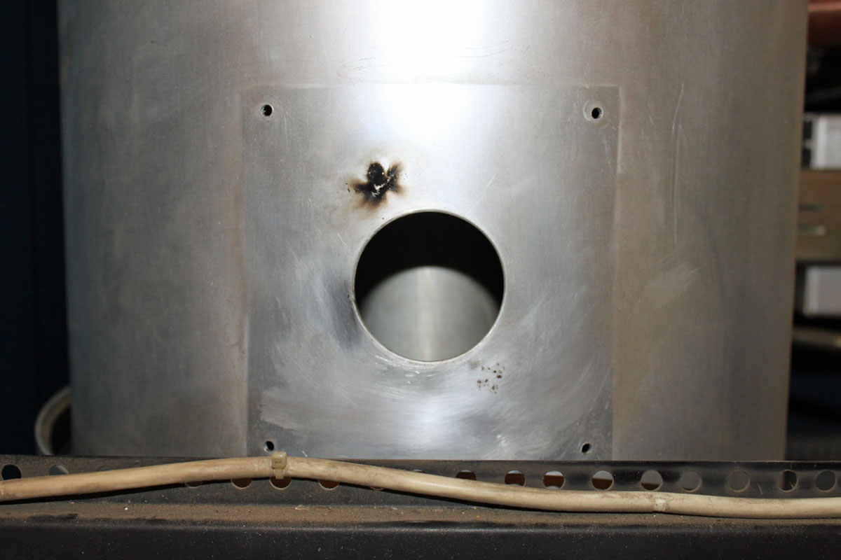
This is the old high voltage feed through hole, arc mark clearly evident.
This is the modified feed through/bypass configuration.

While doing this work, I removed the tube and put a plastic sheet in the bottom of the PA cavity and around the HV parts at the bottom of the transmitter. Somehow, getting aluminum filings in the tube socket seemed like a bad idea. I also thoroughly vacuumed out the entire transmitter once all of the metal work was done.
I removed the Kapton capacitor plates from the old feed-through arrangement and reinstalled the Teflon insulating plates to keep the air flow out of the tube cavity going in the correct direction. The new capacitor looks very beefy, perhaps it will never fail again.
Once the installation work was done, I brought up the transmitter first with no screen and no connection to the tube anode. Then with the tube connected, and finally with the screen supply turned on. The tuning needed a brief touch up but all in all, the transmitter came up and ran well with the new feed-through arrangement.


I love the list prices of the individual pieces of hardware. Makes you wonder how they can sell the transmitter as a unit so inexpensively, considering all the $3 screws, nuts, and washers it must have. Think of how much money you could have saved the customer if you just bought the proprietary parts and went to your local hardware store for the rest.
Sure, order the proprietary parts, wait for them to come in, then run around to the hardware store looking for the appropriate brass screws, bolts, washers and nuts all the while the station is still off the air. Of course, this will require more than one trip, as something is always missed the first time.
By the time all of the expenses and labor is tallied up, it would be more expensive to do it your way then just ordering the retrofit kit and installing it.
Aside from that, I am not sure if the individual parts are available for sale
Bob, in addtion to Paul’s point about the time lost, with transmitter parts some of what you’re paying for is the price of keeping all that stuff on the shelf at the manufacturer’s warehouse *and* for them to have checked out the mod before you’re trying to do it to your transmitter. They *know* it will work with the parts they have spec’ed. …Will it work with the generic replacement hardware? Maybe. Maybe not. Why roll those dice if you don’t have to?
RCA used to be just scary good about parts support for old transmitters, but it wasn’t cheap — and it wasn’t cheap because they had heaps and piles of parts going way, way back, and an up-to-date inventory of them, and small staff to keep track of it all. The entire collection was moved many times. (I think it ended up at Thales.)
If there’s very much RF power involved or high voltage and especially at the higher frequencies, there are plenty of ways for things to go wrong. The best chance of success is to go with OEM parts whenever you can get them.
I do have to say that the details of the RF output connection are heart-warming: wattmeter sampling section right there, pressure gauge at the gas inlet, and (presumably) ground tie: amenities one rarely saw at the small stations back when I was doing contract engineering. (I think it was uphill both to and from the transmitter buildings, in a foot of snow all year ’round, but that’s another story).
The mod kit is a nice clean install, especially in light of how much metal work you had to do.
The step-at-a-time start-up is always good practice with HV — it got a little too exciting sometimes with UHF TV finals: the big IOTs ran 36 kV at a couple of Amps! The lights kind of blink if you missed something and the rig crowbars. 🙁 With little ham rigs, I put a light bulb in series with the AC for initial start-up, which limits worst-case primary current to whatever the bulb draws. (Pick the rating to suit the expected normal current.)
I had to remove that section of transmission line and the cabinet brace below it so I could drill the mounting holes for the back of the new feed thru enclosure. I learned quite a bit about a 30 year old transmitter during this project. Truth be told, these are very well though out units, and as I recall, they were not terribly expensive either. The only downside these days is the 4CX3500A tube, which no one seems to be able to make right anymore.
I should have taken a picture of the inside of the PA cavity but I was a little bit too busy to think about it.
Next trip up, I think I will bring the spectrum analyzer and look at the harmonic levels in the transmitter room just to make sure there are no problems.
Where you able to feed the exciter into the antenna to get them on the air, at reduced power while you worked on the TX?
Hopefully they will think of a aux transmitter, even something small, to keep them on the air during these outages.
I think I was one of the first to have that capacitor problem. I had a pair of FM-5A transmitters we installed in the late 80’s. It was the first parallel set of transmitters BE built of that series. We needed 10 KW and they were not making one yet. If you find an old hard cover BE catalog and see a 10 KW made of parallel 5’s, that is my transmitter.
Anyway we started having those issues right from the start. BE could not figure out what was going on. They had me try a number of different things. Finally they sent me the cap from the 30/35 KW they were making then. That was the type of capacitor shown in the pics that mounted on the outside of the cavity. I think I installed the first one ever, but it stopped the problem. They sent me a second one for the other half of the transmitter. That rig is still my backup.
Do you have an electronic copy of the factory service manual for the BE FM 3.5A transmitter?