The Ubiquiti Nano-Beam

I installed one of these wireless links between two transmitter buildings recently.  The Ubiquiti gear is not my first choice, however, the client insisted that we use this equipment likely because of its inexpensive nature (less than $65.00 per unit).  My overall impression is so-so.  They are fairly easy to set up; the AirOS is intuitive and easy to navigate around.  I had to upgrade the firmware, change the default user name and password, assign IP addresses, subnet mask, gateway information, SSIDs, security parameters, etc.  All of that was very easy to figure out.  My grip is this; it seems the hardware is a bit plastic-y (e.g. cheap).  I know some of the Ubiquiti models are better than others.  I hear good things about the airFiber units but they still don’t compare to the Cambium/Canopy gear.

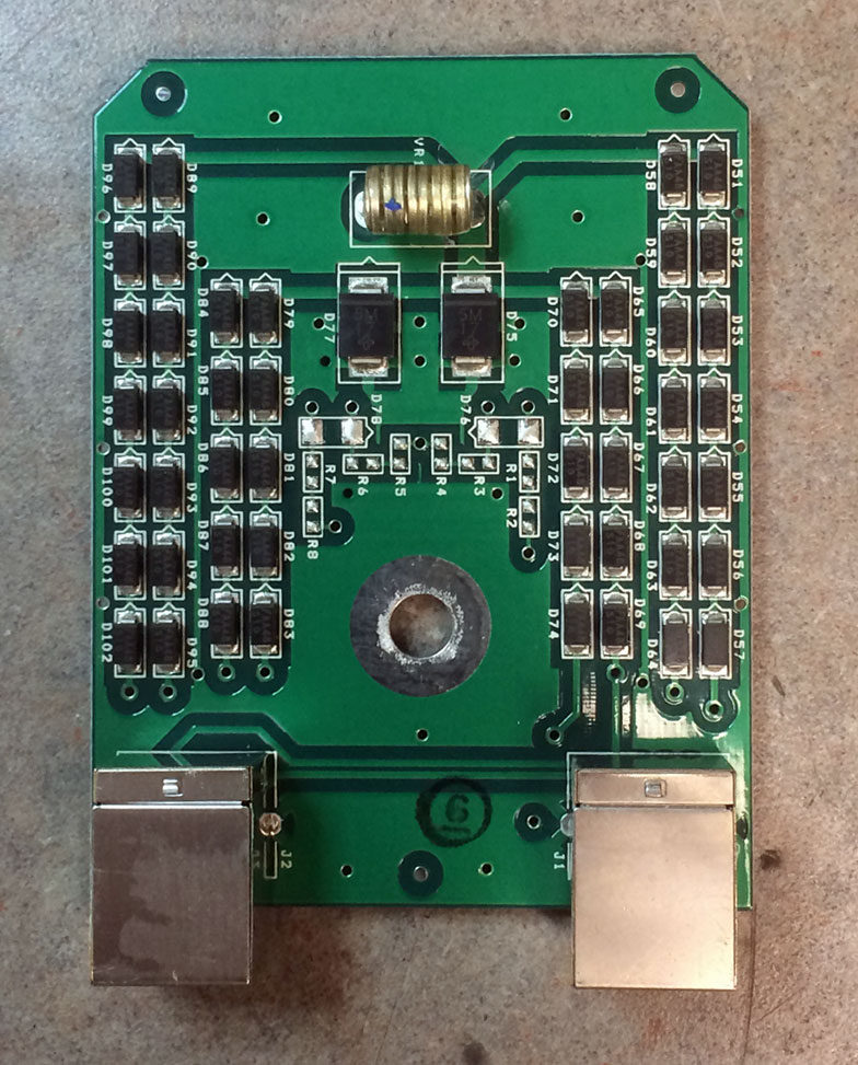
For this installation, I used the shielded Ubiquiti “Tough Cable” with the shielded Ubiquiti RJ-45 connectors and Ubiquiti Ethernet Surge Protectors.  When making the Ethernet cables up, I made sure the shield drain wire was connected to the metal body on the RJ-45 connector.  I tested everything with my trusty Fluke Microscanner cable verifier which also shows continuity for the shield.  I am still not completely confident that the outdoor units will survive a lightning strike on the 898-foot (273.7 meter) guyed tower nearby.  Time will tell.

The system has a wireless path length of about 200 meters plus another 60 meters or so of Ethernet cable.  Latency when pinging the gateway across the entire network is about 3 to 4 ms (laptop>switch>nanobeam<->nanobeam>switch>gateway).  The network is being used for remote control/monitoring of transmitters and backup audio via Comrex Bric link II IP CODECs.

screen shot; Nano Beam Air OS
screenshot; Nano Beam Air OS v7.2.2

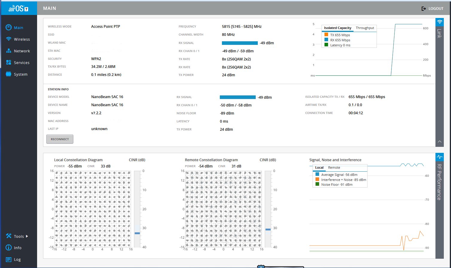
On the plus side, the 802.11ac link is very fast; 650+ Mbps unwashed link speed is pretty impressive.  Strip off the wireless LAN headers and that likely translates to greater than 500 Mbps goodput.  Also, the inexpensive nature of these units means that we can keep a few spares on hand in case something does suffer catastrophic damage due to a storm.  The AirOS v.7 is pretty cool with the RF constellation and other useful tools like airView (spectrum analyzer with waterfall display), discover, ping, site survey, speed test, traceroute, and cable test.

After installing the updated firmware, which fixes a major security flaw with the web interface, the link was established with three mouse clicks.  After that, I ran speed tests back and forth for several minutes.  Basically, the speed on the LAN is reduced because of the 100 Mbps switch.  Even so, that should be more than enough to handle the traffic on this segment of the network.

Lightning protection for WLAN links

More and more wireless LAN links are being installed between the transmitter and studio.  Often these links are used for network extension, remote control, site security, VOIP telephony, and sometimes even as a main STL.  These systems come in several flavors:

  • Moseley LAN link or similar system.  Operates on unlicensed 920 MHz (902-928 MHz) band.  Advantages: can use existing 900 MHz STL antennas, can work reliably over longer distances, transmitter, and receiver located indoors.  Disadvantages: slow, expensive
  • ADTRAN TRACER or similar system with indoor transceivers and coax-fed antenna systems.  Operates on unlicensed or licensed WLAN frequencies.  Advantages: fast, transmitter and receiver located indoors, can be configured for Ethernet or T-1/E-1 ports.  Disadvantages; expensive
  • Ubiquiti Nano bridge or similar system where the transceiver is located in the antenna, the system is connected via category 5/6 cable with POE.  Operates on unlicensed or licensed WLAN frequencies.  Advantages; fast, relatively inexpensive.  Disadvantages; equipment located on the tower, difficult to transition base insulator of series fed AM tower.
  • Ubiquiti Rocket or similar system where the antenna and transceiver are separate, but the transceiver is often located on the tower behind the antenna and fed with category 5/6 cable with POE.  Operates on unlicensed and licensed WLAN frequencies.

For the first two categories of WLAN equipment, standard lightning protection measures are usually adequate:

  • Good common point ground techniques
  • Ground the coaxial cable shield at the tower base and at the entrance to the building
  • Appropriate coaxial-type transmission line surge suppressors
  • Ferrite toroids on ethernet and power connections

For the second two types of WLAN equipment, special attention is needed with the ethernet cable that goes between the tower and POE injector or switch.  Shielded, UV-resistant cable is a requirement.  On an AM tower, the shielded cable must also be run inside a metal conduit.  Due to the skin effect, the metal conduit will keep most of the RF away from the ethernet cable.  Crossing a base insulator of a series excited tower presents a special problem.

The best way to get across the base insulator of a series excited tower is to use fiber.  This precludes the use of POE which means that AC power will be needed up on the tower to power the radio and fiber converter.  This may not be a huge problem if the tower is lit and the incandescent lighting system can be upgraded to LEDs.  A small NEMA 4 enclosure can house the fiber converter and POE injector to run the WLAN radio.  Some shorter AM towers are no longer lit.

Another possible method would be to fabricate an RF choke out of copper tubing.  This is the same idea as a tower lighting choke or a sample system that uses tower-mounted loops.  I would not recommend this for power levels over 10 KW or on towers that are over 160 electrical degrees tall.  Basically, some 3/8 or 1/2-inch copper tubing can be wound into a coil through which a shielded ethernet cable can be run.  Twenty to twenty-five turns, 12 inches in diameter will work for the upper part of the band.  For the lower part, the coil diameter should be 24 inches.

In all cases where CAT 5 or 6 cable is used on a tower, it must be shielded and the properly shielded connectors must be used.  In addition, whatever is injecting power into the cable, ether POE injector or POE switch must be very well grounded.  The connector on the shielded Cat5 or 6 cable must be properly applied to ensure the shield is grounded. 

In addition to that, some type of surge suppressor at the base of the tower is also needed. Tramstector makes several products to protect low voltage data circuits.

Transtector APLU 1101 series dataline protector
Transtector APLU 1101 series data line protector

These units are very well made and designed to mount to a tower leg. They come with clamps and ground conductor designed to bolt to a standard copper ground buss bar.

Transtector APLU 1101 series dataline protector
Transtector APLU 1101 series data line protector

There are various models designed to pass POE or even 90 VDC ring voltage.

Transtector APLU 1101 series dataline protector
Transtector APLU 1101 series data line protector

This model is for POE. The circuit seems to consist mostly of TVS diodes clamping the various data conductors.

As more and more of these systems are installed and become a part of critical infrastructure, more thought needs to be given to lightning protection, redundancy and disaster recovery in the event of equipment failure.

Fifth Generation WLAN

Like all data-carrying technology, WLAN, or WiFi, continues to evolve into a better, faster, and more robust platform.  The IEEE wireless ethernet specification 802.11ac combines all of the past developments, plus some added features, into one specification.  Here are some of the highlights:

  • Operation on 5 GHz only.  Many more available channels in this spectrum than in 2.4 GHz
  • Increased channel bonding makes wider channels carry more data.  In the 5 GHz spectrum channels are 20 MHz wide and do not overlap.  802.11ac allows for 40, 60, 80 or even 160 MHz channels.  This is great for short distances, longer distances will be prone to greater interference over wider channels
  • Modulation schemes that allow up to 256 QAM.  A 256 QAM constellation is going to look pretty crowded unless it is on a wide channel.  Again, this would be good for short distances.
  • Increased MIMO.  Up to 8×8 MIMO (Multi In Multi Out) which can greatly improve throughput.  MIMO means multiple transmitters and antennas in the same unit.  The first number is the transmitter count the second number is the antenna count.  Thus an 8X8 system will have eight transmitters and eight antennas.  This allowed beam forming by use of phased antenna arrays, which can greatly reduce multi-path
  • MU-MIMO (Multi-User MIMO).  Basically, the access point sends the data frame only to the desired host, thus instead of acting like an ethernet hub sending the frame to every connected host, the AP is acting more like an ethernet switch.
Comparison of 802.11n to 802.11ac

The goal of all of these modifications is to get gigabit transfer rates over WLAN.

What does all of this have to do with radio broadcast, one might ask?  That is a good question.

There are several applications that have to do with remote broadcasting.  Many sports areas, nightclubs, or other likely places to be broadcasting from have WIFI installed.  Using a laptop with an AoIP client installed not only can connect to the studio for audio delivery, but the same laptop can also use RDP or VNC to control the station’s automation computer as well.  This means easier integration of the remote into voice-tracked or syndicated programming.

Secondly, wireless LAN bridges between the studio and the transmitter site can act as an STL, a backup STL, a remote control return link, a bridge for a network-connected transmitter, a VoIP phone link, IP security camera backhaul, or almost anything else that can send ethernet data.  I have found it useful to simply have a computer available at the transmitter site, even if it is only to download manuals and whatnot.  We have taken several old Windows XP machines and reloaded them with a Linux variant and installed them at various transmitter sites.  It saves the trouble of having to download a manual on the smartphone and then page back and forth across a really small screen to read it.  As for using unlicensed WiFi to link to a transmitter site; the link between the WICC studio and transmitter site runs 78 Mbps most days.  This is a two-mile link over mostly water.  I will say, when there is fog, the link rate drops to 32 Mbps, which is still pretty good, all things considered.

Of course, office network applications; laptops, tablets, smartphones and other personal devices.

Finally, Broadcast Engineers really need to keep abreast of networking technology.  There are many, many applications for WiFi units in the broadcast industry.

CES 2014 and the Digital Radio question

I have been busy of late, however, still keeping abreast of the news of the day.  Along with that, CES 2014 wrapped up recently.  No huge developments, especially when it comes to Broadcasting.  However, there was one item of interest; the updated technical specifications of IEEE 802.11ac.

It is of interest here because of the implications of mobile/portable data developments and their impact on traditional AM and FM broadcasting. The new specification calls for 1.2 Gbp/s per device in the initial release, increasing that throughput to 6 Gbp/s in later releases.  These data rates are for overall transmission, including the WiFi overhead.  Actual usable application data (layers 5-7) would be about 20 to 30 percent less.  Even so, 900 Mbp/s is a phenomenal data rate.  Truly I say to you; this is the future of digital broadcasting.  HD Radio™; may well prove that the “HD” stood for “Huge Distraction.”

The new 802.11ac specification uses MU-MIMO, high-density modulation, larger channel bandwidths, and beamforming technology in the 5 GHz WiFi spectrum.  Of course, the question is, at what distances will this system work?  If it is like conventional WiFi, then 100-200 feet is about all that can be expected.  However, there are also many people interested in wireless broadband (WiMAX) service as an alternative to traditional wired ISPs. For that application, having many outdoor 802.11ac nodes connected by a backbone could potentially blanket a city or campus with free high-speed wireless data.

Example of cjdns network

Along the same lines, there are many people involved in creating mesh networks of various types; be they ad-hoc mobile networks, darknets, bitclouds, etc. Mesh networking is a very interesting topic, for me at least.  The network protocols are getting better and more secure.  WiFi hardware is becoming less expensive and more reliable.  As more and more people put effort into developing protocols like cjdns, local mesh networks will become widespread unless they are outlawed.  You know; because of teh terrorism!!1!!

As it stands today, I can drive for two hours in mostly rural upstate NY and CT streaming my favorite radio programs and have nearly seamless handoffs and very few dropouts.  This is on my three-year-old, beat-up 3G HTC android phone sitting in the passenger seat of my car.

Digital Radio is here, it is simply not the In Band On Channel system that legacy broadcasters have chosen.