There are still many hollow state (AKA tube type) transmitters floating around out there in the broadcast world. High power, especially high power FM transmitters are often tube types and there are many good attributes to a tube transmitter. They are rugged, efficient and many of the well-designed tube units can last 20-25 years if well maintained.
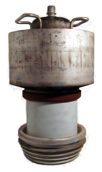
The downside of a tube transmitter is tube replacement. Ceramic tubes, like a 4CX20,000 or 4CX35,000C cost $6-9K depending on manufacture. A well-maintained tube and last 3-4 years, I have had some lasting 8 years or more. My personal record was for a 4CX35,000C that was a final PA tube in a Harris MW50A transmitter. The tube was made by EEV (English Electrical Valve, now known as E2V) and lasted approximately 84,000 hours, which is 9.58 years. When it finally came out of service it looked like it had been through a fire, the entire metal plate body was dark blue. I took it out because the power was beginning to drop a little and it was making me nervous.
This was not an accident, I did it by maintaining the filament voltage and keeping the tube and transmitter clean. The tube filament supplies the raw material for signal amplification. Basically, the filament boils off electrons, which are then accelerated at various rates and intensities toward the plate by various control grids. The plate then collects the amplified signal and couples it to the rest of the transmitter. When a tube goes “soft,” it has used up its filament.
I had a long conversation about this one day with Fred Riley, from Continental Electronics, likely the best transmitter engineer I have ever known. At the time, the consensus was to lower the tube filament voltage by no more than 10%. On the 4CX35,000C, the specified filament voltage is 10 volts, therefore, making it 9 volts was the standard procedure. What Fred recommended was to find the performance “knee,” in other words, where the power began to drop off as the filament voltage is lowered. Once that was determined, set the voltage 1/10 of a volt higher. I ended up running that EEV tube at 8.6 volts, which was as low as the MW50’s filament rheostat would go.
The other important thing about tubes is the break-in period. When installing a new tube, it is important to run only the filament voltage for an hour or two before turning on the plate voltage. This will allow the getter to degas the tube. New tubes should be run at full filament voltage for about 100 hours or so before the voltage is reduced.
Tube changing procedure:
- Remove power from transmitter, discharge all power supply caps to ground, hang the ground stick on the HV power supply.
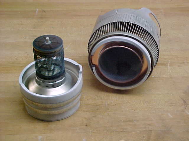
- Remove the tube, and follow manufacturer’s procedures. Most ceramic tubes come straight up out of their sockets (no twisting).
- Inspect socket for dirt and broken finger stock. Clean as needed. Finger stock, particularly in the grid section, is important for transferring RF. Broken fingers can lead to spurs and other bad things
- Insert new tube, follow manufacturer’s recommendations. Ceramic tubes usually go straight down, no twisting.
- Make all connections, remove grounding stick, half tap plate voltage supply if possible, close up transmitter
- Turn on filaments and set voltage for manufacturers’ recommended setting. Wait at least 90 minutes, preferably longer.
- Turn on plate voltage and tune transmitter. Tune grid for maximum current and or minimum reflected power in the IPA. PA tuning should see a marked dip in the PA current. Tune for dip, then load for maximum power.
- Turn off transmitter, retap plate supply for full voltage
- Turn on transmitter and plate supply, retune for best forward power/efficiency ratio.
- After the 100-hour mark, reduce filament voltage to 1/10 volt above performance knee.
Of course, every transmitter is slightly different. There may not be a dip in the plate current if the transmitter is running near its name plate rating, in which case one would tune for maximum forward power.
This system works well, currently one of the radio stations we contract for has a BE FM20T with a 4CX15,000A that has 9 years on it, still going strong.