
I found this in the great clean out of 2010, Bridgeport, Connecticut. Once upon a time, I had a slightly newer version of this, I think from 1972 or so. This version is from 1964 and gives a complete rundown of most small tubes that were manufactured back then.
There is something about a well-designed, well-maintained piece of tube gear. I remember an old Collins tube console that was in a production room at a small AM station. The console went dead (the paper clip shorted the B+) and I fixed it.
I recall listening to the test recording of my own voice from a reel-to-reel machine when I fixed the console. It sounded better than I’d ever heard it, not that I have a great radio voice, by any means.
A tube is a voltage amplifier versus a transistor, which is a current amplifier. A tube does not have the same fidelity as a transistor, as the voltage reaches its peak, it gets a little fuzzy, adding some distortion and harmonics. Tube gear adds warmth, what a musician might call Timbre. The combination of fundamental frequency and varying amplitudes of harmonic frequencies allow a listener to tell the difference between a piano and a guitar playing the same note.
This is what the current crop of tube mic preamps and other tube products tries to reproduce. Several companies have come out with an amplifier design that has mostly transistors and one tube, usually a 12AX7. Unfortunately, at least in my opinion, they fall a little short. If you want to have the “tube sound,” it needs to be all hollow state.
What is intriguing to me are the schematic diagrams in the back of the book. There is one for an audio amplifier:
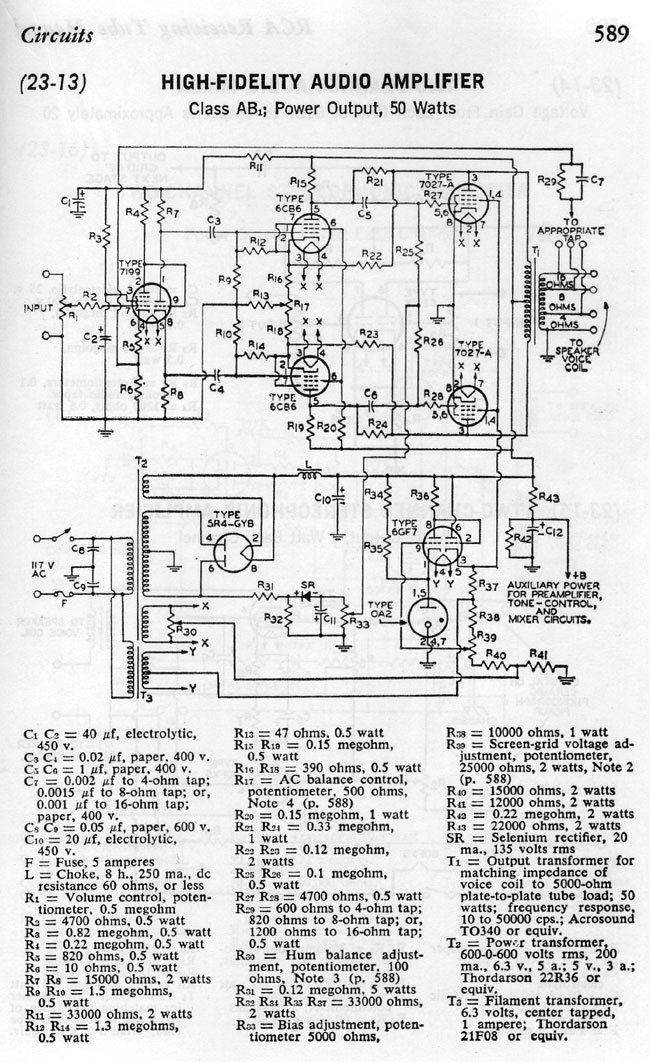
This is a single-channel unit, for stereo, it would need to be duplicated. Also, I would lose the tube rectifier in favor of a solid-state full wave bridge, which would simplify T2 somewhat. The OA2 could also be changed to a diode. Looks like unbalanced audio, which could be modified with an input transformer.
Another interesting diagram is this one, which can be used as a mic preamp:
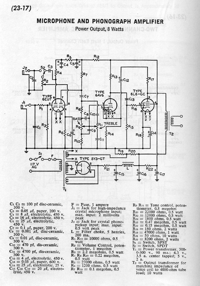
That looks like a pretty solid design, a few tweaks here or there to add some gain reduction and some type of output level adjustment and I would be a really cool piece of gear. Again, the tube rectifier could be replaced with something solid state. The output transformer would likely have to be changed to something like 600 ohms.
Couple that to something like this, the Collins 26U compressor/limiter, and one would have a great sounding microphone processor:
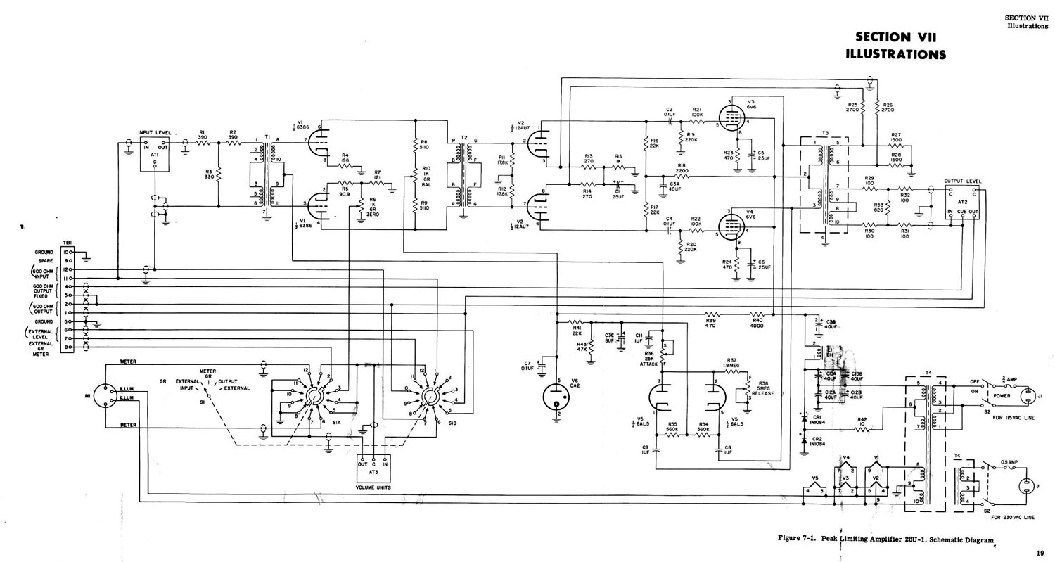
Looks pretty cool. R10 is used to balance the two plate currents. I would be interested in the transformer values, input/output impedances, voltages, etc. The 6386 tube is very hard to find these days, a good substitute would be a 5670 which is still made by several manufacturers.
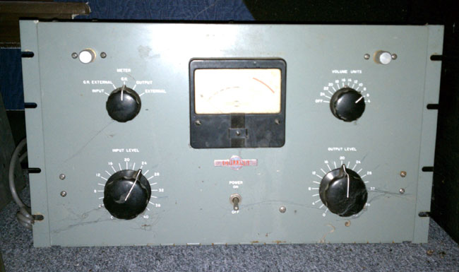
Update: This is a picture of a Collins 26-U sitting on my boss’s floor.
A great online source for tube information is Electron Tube Data Sheets.
If I have some time this winter, it may be a fun project to fool around with.