Differential Audio

Most professional audio facilities use differential audio or balanced audio within their plants.  The main reason for this is noise rejection, which was discovered by the early pioneers of wired telephony back in the late 1800s.  Balanced audio is created by generating two audio signals that are 180 degrees out of phase using either a transformer or an active device.  These are usually labeled High and Low, + and – or something similar.  Those two audio signals are then transmitted across some distance and recombined at the far end, again by a transformer or some active device.

Noise rejection, differential signaling. "DiffSignaling" by Linear77 - Own work. Licensed under CC BY 3.0 via Wikimedia
Noise rejection, differential signaling. “DiffSignaling” by Linear77 – Own work. Licensed under CC BY 3.0 via Wikimedia

When an interfering signal is picked up, it is transmitted along both sides of the balanced audio circuit until the signals are recombined.  During the re-combining process, common mode interference is canceled out, as it becomes 180 degrees out of phase with itself during the re-combining process.

Differential signaling is used in analog audio, digital audio (AES/EBU), HDMI, Display Port, USB, Ethernet, POTS lines, ISDN, T-1/DS-1, E-1, etc.   It is a fairly simple concept, but one of the basic building blocks in broadcast studios.

When a studio project was completed at a disused studio/transmitter site location, a certain amount of RFI was being induced on the studio microphones by the unassociated FM transmitter in the next room.  The problem with microphone-level audio is the relatively low level of microphone output, which requires a good deal of amplification.  The amplifiers in this console have active balanced inputs, which might not be exactly 180 degrees out of phase.  In this installation, microphone-level audio was run about 20-25 feet on a standard microphone cable then it was converted to Cat 6 cable before going into the console.  It may have been better to use the shielded Cat 6 cable for the longer runs as it likely has better common mode rejection than standard mic cable. Another option might have been Star Quad cable.  However, none of those things were done.

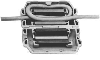
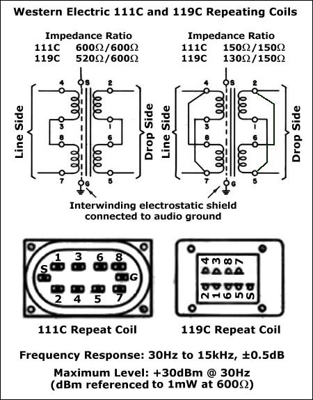
Western Electric was the manufacturing arm of Bell Telephone.  In their day, they made some really good equipment.  One such piece is the WE-111C repeat coil.  These can be configured for either 600/600 ohms, 600/150 ohms, 150/150 ohms,  or 300/300/300/300 ohms impedance ratios.  Since this is microphone-level audio 150/150 ohms is the appropriate setting.

WE 111 repeat coil, one of the best such transformers ever made

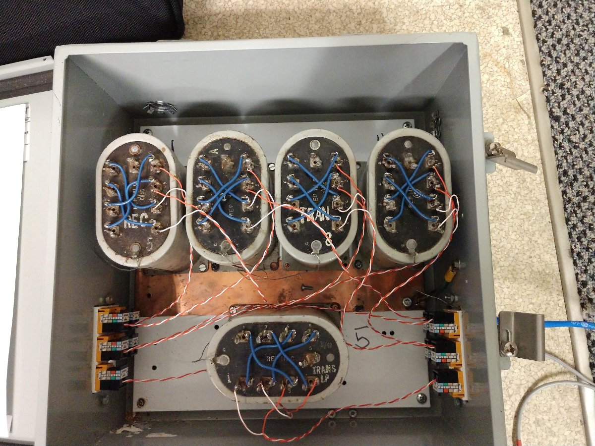
Over the years, I have found many of these transformers discarded at various transmitter sites and studios. There are five microphones feeding this console. I mounted five of these coils in a sturdy metal enclosure and wired them with RJ-45 jacks to be compatible with the Studio Hub wiring equipment used in this studio installation.  I also grounded each unit to a piece of copper strap, which is connected to a grounding lug on the side of the unit.

Western Electric 111C repeat coils mounted in box

I swept the coils from 20Hz to 20kHz:

WE 111C coils, 20Hz sweep
WE 111C coil 20kHz sweep

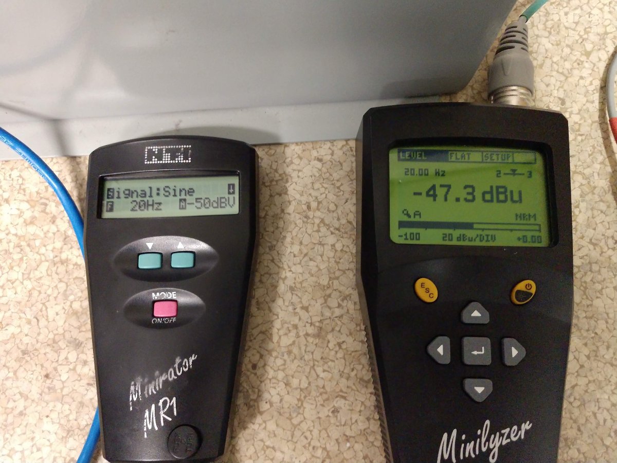
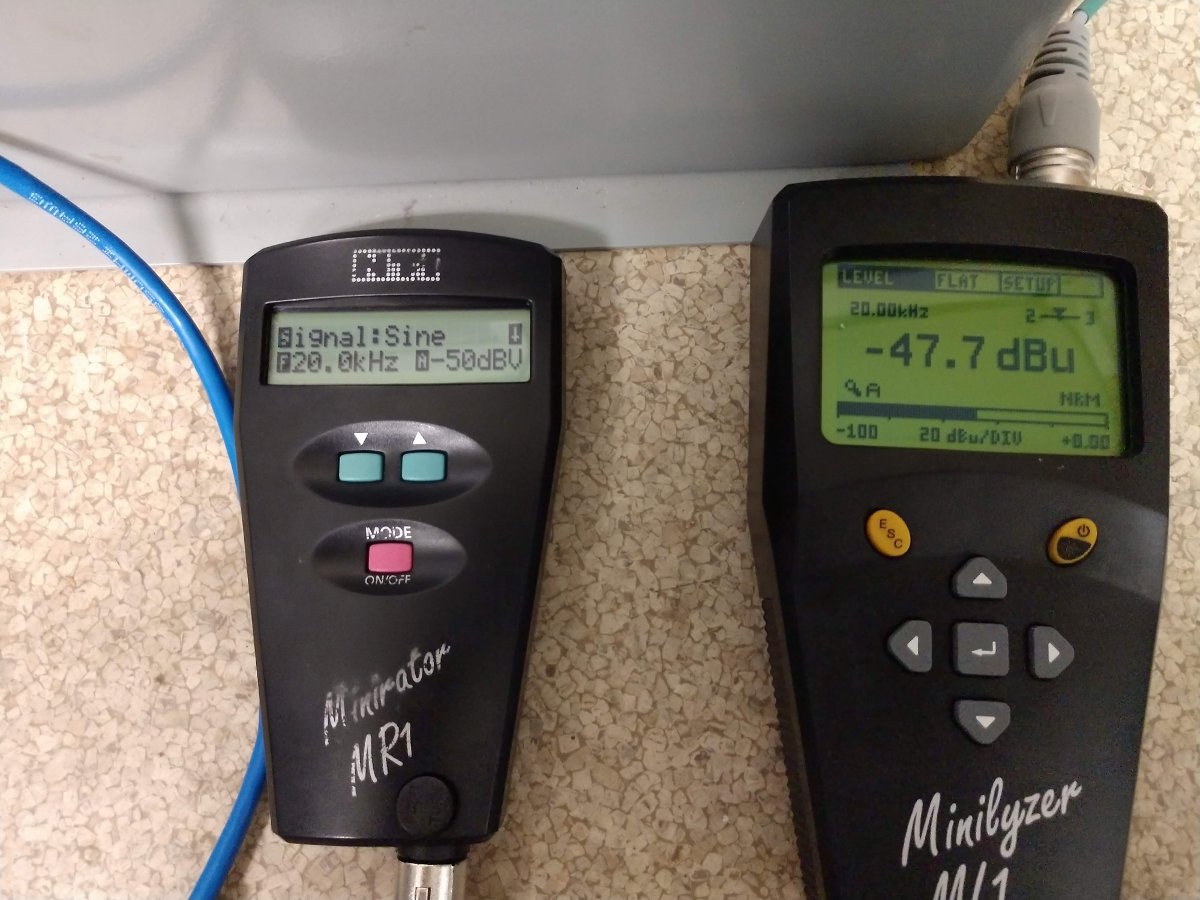
This shows a 0.4 dB difference from 20 to 20,000 Hertz, thus they are all nearly flat which is a pretty cool feat of engineering.  I would estimate the age of these transformers is between 50 to 60 years old.

These coils isolate each microphone from the microphone preamp in the console.  This completely eliminated the FM RFI and solved the problem.

Blanketing Interference and RFI

Blanketing interference refers to the phenomenon of receiving radio signals on devices not designed to do so.  In broadcast radio, this is defined for AM stations in part 73.88 as:

The licensee of each broadcast station is required to satisfy all reasonable complaints of blanketing interference within the 1 V/m contour.

And for FM stations, it is part 73.318:

Areas adjacent to the transmitting antenna that receive a signal with a strength of 115 dBu (562 mV/m) or greater will be assumed to be blanketed.

Any interference to any device with that signal contour is blanketing interference.  73.318 further states that:

permittees or licensees who either (1) commence program tests, or (2) replace their antennas, or (3) request facilities modifications and are issued a new construction permit must satisfy all complaints of blanketing interference which are received by the station during a one year period.

I have always taken a more pragmatic approach to interference complaints.  Rather than pass the buck and tell the homeowner or business owner that it is not our (the radio station’s) problem, I’d go and try to help them out.  Generally speaking, the interference problems are close to the transmitter site, so on the next trip to that site, I would bring RFI filters and my 25 years of RF experience and solve the problem.  I would like to think this helps the station’s and the company’s image in the community.

Most of the problems are pretty easily solved, although once in a while, I have come on some head-scratchers.  An AM station playing on the outlets in a guy’s garage, the mic cords on a church PA system, and an off switch on a blender, off all things.  The Bare Naked Ladies had a line in the song Light up my Yard: “we can dance to the radio station that plays in our teeth.”

What I have found is to start with the simple stuff first, check the ground on the electrical service entrance panel.  One might be surprised to find it disconnected, corroded, or missing completely.  On more than one occasion, I fixed all of the RFI problems with a simple turn of the screw holding the ground wire to the grounding electrode.  In my experience, this is the most common single failure point.  A disconnected ground will cause the entire neutral wiring system to act like a giant AM antenna, with all sorts of bad outcomes.

RFI suppression ferrite

Most often, telephone answering machines, cordless phones, and other devices powered by wall warts are suspect.  Those devices do not have a path to ground.  A few turns of all the wires coming and going from said device around a ferrite core such as a snap on TDK RFI EMI filter available from Mouser will take care of it.  Mouser has several different versions available.

Occasionally, one needs to put on a detective hat and do some footwork.  Mast mount TV antenna preamps can cause untold heartache and problems.  One such incident involved the second harmonic of an FM station falling exactly on channel 11’s audio frequency.  This was affecting several houses in a one-block area.  I finally found the problem at one of the complainant’s houses when I pulled the TV out and found the preamp power supply.  Unplugging it made all the problems go away (I hate Radio Shack).

Usually, the process of elimination will discover the problem and thereby reveal a solution.  The aforementioned church incident was discovered after I began unplugging microphone cords from the back of the Mackie mixer in the choir loft.  It turns out several mic lines were plugged into the back of the mixer, unused and unterminated, creating a large long receiving antenna on the cable shield, which happened to be aligned perfectly to pick up RF from an AM station.