Right after Tropical Storm Irene, it was noted that the STL signal strength at the WHUD transmitter site was low. Normally it was 300+ µV, but now reading around 100 µV, which is a problem. Upon further investigation, it was revealed that the STL transmitter on the intermediate hop had higher than normal reflected power.
Time to call the tower crew.
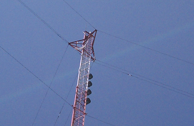
The STL transmit antenna for WHUD’s STL (WPOU464) hop is a Scala Paraflector (PR-950), mounted at the 280-foot level on this tower:
Scala PR-950 on a guyed tower
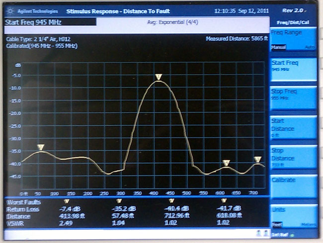
The fact that it happened after a major storm and the transmitter was showing higher than normal reflected power indicates a problem with either the antenna or the jumper between the 7/8″ Cablewave coax and the N connector on the antenna. A measurement with a spectrum analyzer shows very high return loss:
WHUD STL antenna return loss
This shows the distance to fault 413 feet, with a return loss of -7.4 dB. That distance is either near or at the antenna and -7.4 dB indicates a lot of reflected power. We had the tower climber take apart the jumper connections and terminate the jumper with a known good 50-ohm load. The return loss did not change. We then had him swap out jumpers and reconnect to the antenna. That did the trick:
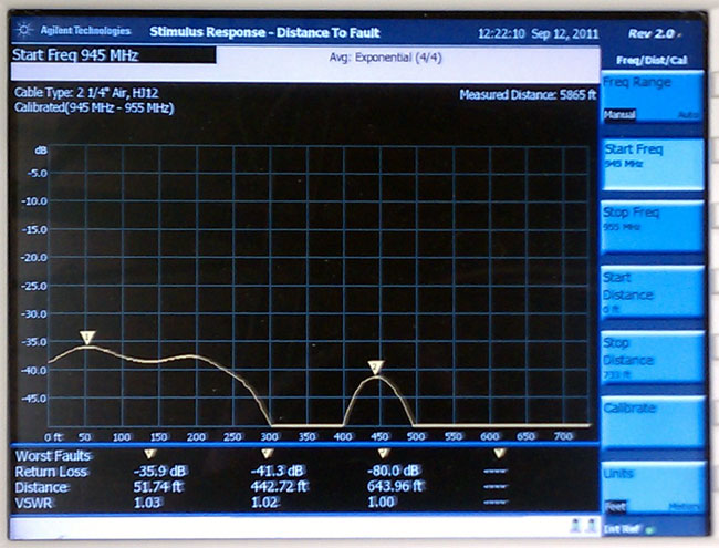
WHUD STL antenna with new jumper
Much better, most of the power is now being radiated by the antenna, the VSWR is 1.02:1. The impedance bump at 51 feet is a sharp bend in the coax where it is attached to an ice bridge. Reconnecting the transmission line to the transmitter and turning it on confirms that all is normal again. The problem with the jumper was found in one of the connectors, it was full of water.
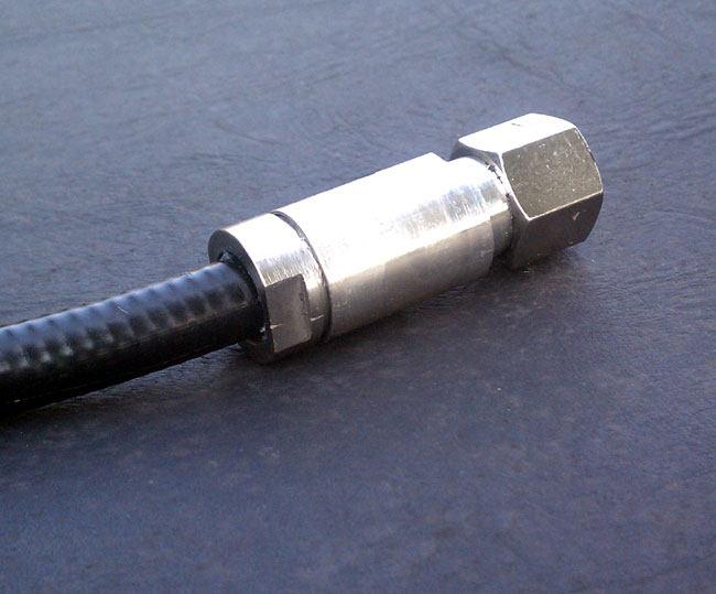
Water-contaminated Andrew flexwell connector
I cut away the boot, water had entered the connector from the back because waterproofing and tape was not applied all the way to the coax. This was installed in 1998 when the station moved from Peekskill to its current location in the town of Fishkill. The fact that it happened now in the nice weather when Mt. Beacon is still accessible and not in the middle of winter means the radio gods are smiling on us.
Not that I am a glutton for punishment or anything, but I enjoy troubleshooting. There is a certain satisfaction in the analytical aspect of tracking down a problem and fixing it, hopefully in a permanent fashion. Figuring out where a problem is requires a good bit of detective work;
Examining the clues; what happened before the failure, what are the fault indications, are there any external factors
Round up the usual suspects; a good maintenance log is helpful here to track re-occurring failures. If the failure cannot be attributed to an external source (such as a power surge or lightning storm), what was the last thing that was changed or worked on?
Following the trail back to the origin; Often the first failed part found is a symptom, not the actual problem. It takes some skill in reading schematics and making sense of a failure to trace it back to the real problem.
It can sometimes be exciting, like turning on the 25 KV high voltage supply and having big blue flashes issue forth from the top of the transmitter. Sometimes it can be quite frustrating, like when the station owners refuse to spend money to fix a problem. Sometimes it can be dull, like fixing the same problem over and over again because of the previously stated money problem. It’s also disheartening when the problem was caused by the stupid DJ spilling soda in the console. Not that all DJs are stupid, just the ones that spill things into consoles.
The challenge of finding the root cause can often be enlightening. I have often discovered unrelated problems waiting in the wings while investigating the why of an outage. It is great to fix those things before they burn the house down, but this approach often goes unnoticed by the ownership or management. Lately, for some reason, an ounce of prevention goes unnoticed or unappreciated.
There is quite a bit of science to troubleshooting, but there is some combination of personal traits that make a good troubleshooter. These are:
Inquiring or curious disposition. It is fairly easy to get to the first failed module or part. Discovering the reasons behind the failure and or getting down to the component level takes a good deal more effort.
Patience. This goes with the second part above, it takes some stick-to-it-tive-ness to trace out the not readily apparent problem.
Good analytical skills. Often failures generate a cause-and-effect scenario. The effects can be startlingly distractive and mask the causes and the underlying problem.
Ability to view the large picture. This is critical to discover outside influences and other issues that are indirectly connected to the system or issue at hand.
Ability to analyze the system design. This requires background training and experience to look at a circuit diagram and discover non-error-tolerant systems. Sometimes these systems can be modified for better fault tolerance.
Poorly designed equipment is the bane of the broadcast engineer. Equipment manufacturers can sometimes fail to follow two key principles: KISS and maintainability. KISS stands for Keep It Simple, Stupid. There is no better design criteria than the KISS principle. Adding layers of complexity increases the failure expectations. Maintenance can be something as simple as cleaning or changing air filters. Making maintenance tasks difficult almost ensures that they will not be done.
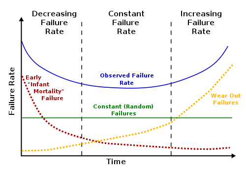
Bathtub design curve
Eventually, all things wear out. It also takes some large-picture skills to know when it is time to replace equipment and that can vary greatly from situation to situation.
Mouser Electronics has created a mobile web edition for its online store. This is a handy tool for searching, cross-referencing, and ordering parts. Mouser has a large stock and they ship quickly. Time once was that you could run down to the local electronics store and get just about anything you needed. Even Radio Shack carried a fair amount of small parts, tools, connectors, and so on. Since then, the local electronics shop has closed and Radio Shack’s inventory gets smaller every year. Using a large parts supply company like Mouser or Allied is necessary if any type of troubleshooting and repair is undertaken.
I like the Mouser Mobile site because there is no app to download and install. One simply points the web browser on any mobile device to mouser.com and it will automatically redirect to the mobile site. If that does not work, then m.mouser.com will. The mobile website is easy to browse around, and if needed, a quick call can be made by hitting the little phone icon. Here is more in a video:
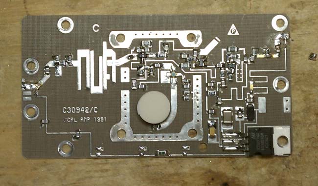
A quick glance at almost any circuit board these days will show that almost all of the components are surface-mounted. They are small rectangles or squares that sit on top of the circuit board. This is different from the through-hole components that were used for many years and are still found in older equipment. There are radio engineers who feel that surface mount components are too hard to work on, thus the boards are not repairable.
California Amplifiers C band block down converter
As with anything in the engineering field, there needs to be a cost/benefit analysis. Most computer component boards, things like NICs, modems, sound cards, VGA cards are very inexpensive, and often times it would be more expensive to repair the board than it would to buy a new one. In other situations, however, local repair of circuit boards makes good sense and can be a good learning tool.
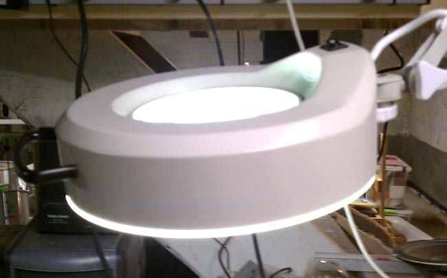
Consoles and transmitters offer some good opportunities for local repair, provided the schematics are available. SMT component troubleshooting is the same as through-hole troubleshoots, except the components are smaller. That is where a magnifying glass comes in handy. I purchased a magnifying glass/light to work on SMT boards.
three diopter magnifying lamp
Soldering and unsoldering techniques are also different. A temperature controlled soldering iron with a small tip is important. I find the easiest way to unsolder a component is with solder wick. Once most of the solder has been wicked up, a brief touch of the iron and the component will come off. Small resistors and capacitors are fairly rugged, but should not be overheated. Semiconductor components such as diodes, transistors and ICs are susceptible to heat damage and Electro Static Discharge (EDS). A grounding wrist strap should always be used when handling semiconductor components. Soldering iron temperature should be enough to quickly melt the solder and heat the connection surface without overheating the SMT component. Lead free solder requires slightly higher temperatures than the traditional 60/40 rosin core.
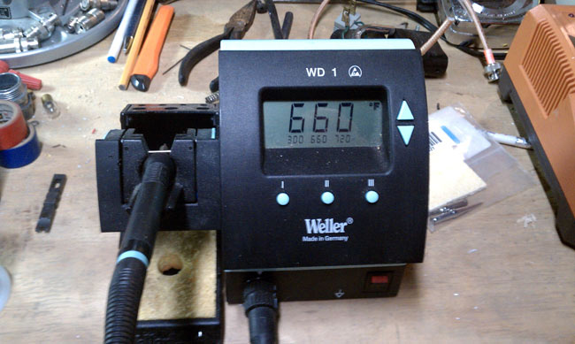
Weller WD1 temperature-controlled soldering station
A temperature-controlled soldering station is a must. Too much heat will damage components and boards, too little will make soldering SMT an arduous task.
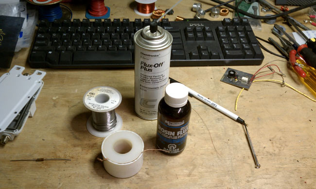
Soldering supplies
Other soldering supplies include liquid flux, desoldering wick, flux remover and 55/40/5 solder. The desoldering wick makes it easy to clean up an errant solder deposits and is the best way to desolder surface mount components. I have had limited success using a solder pump on surface mount boards. They do come in handy for RF MOSFETS, which have large tabs, often with liberal amounts of solder applied at the factory.
Soldering new components:
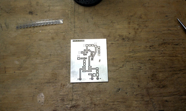
HF receiver preamp SMT board
A typical 0.1 uf capacitor is placed on the surface mount board and ready to be soldered. These components are all small, but I would characterize this as a medium sized one. There are some very small diodes, ICs and other devices that require the magnifying glass to identify pins and polarity.
The best way that I have found to solder components onto a surface mount board is to use a little bit of liquid flux on the board.
Using tweezers or small needle nose pliers, place the component.
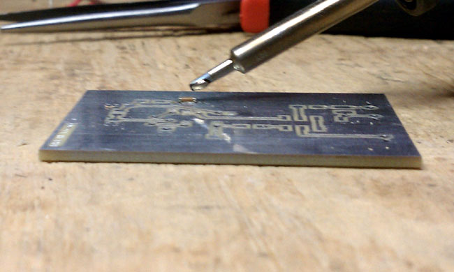
Soldering 0.1 uf bypass cap on SMT board
Wet the end of the soldering iron with a little bit of solder.
Using the placing tool, hold the component in place and touch one of the pads with the soldering iron. This should tack the component in place. Solder the component to the other pad using the soldering iron and solder. Then come back and touch up the tacked side. I have found that 600 degrees F is a good temperature to quickly melt the solder, while not heating up the component too much.
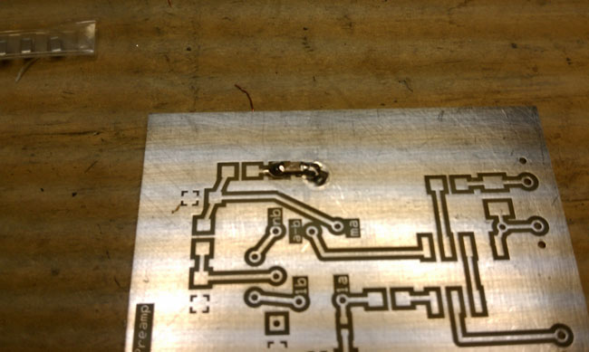
HF receiver preamp with bypass capacitor soldered
Sorry I could not get pictures of the actually process, I don’t have enough hands to hold the soldering iron, hold the component down and take a picture.
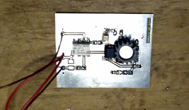
HF preamp based on Norton 1N5109 design
The completed preamplifier. I have been calling this an HF preamp, because that is its intended use. In practice, this preamp should work well from 50 KHz up to about 75 MHz, with 3dB points at 30 KHz and 100 MHz.
Norton HF preamp Schematic
The Norton design is an inverse feed back and using the 1N5109 transistor, which has input and output impedance of 50 ohms, makes it simple to implement. In testing, I found this unit has about 10-11 dB of gain with about 4 dB of noise. The use of SMT makes the design stable and I didn’t see any evidence of oscillations when testing it. More on the preamp here. I installed it out at the base of my K9AY antenna and it can be remotely turned on and off as needed. My main reason for wanting it is to overcome the 6.5 dB signal loss in the four port hybrid receiver coupler and transmission line I use. Truth be told, most of the time it is off.