North Adams Tower Collapse

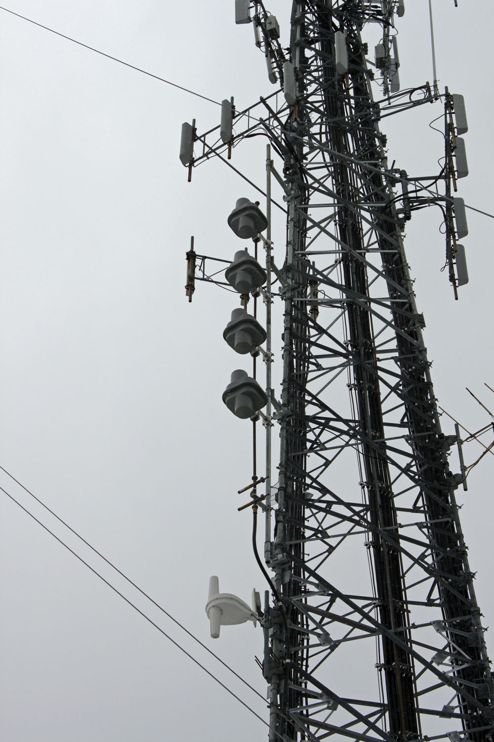
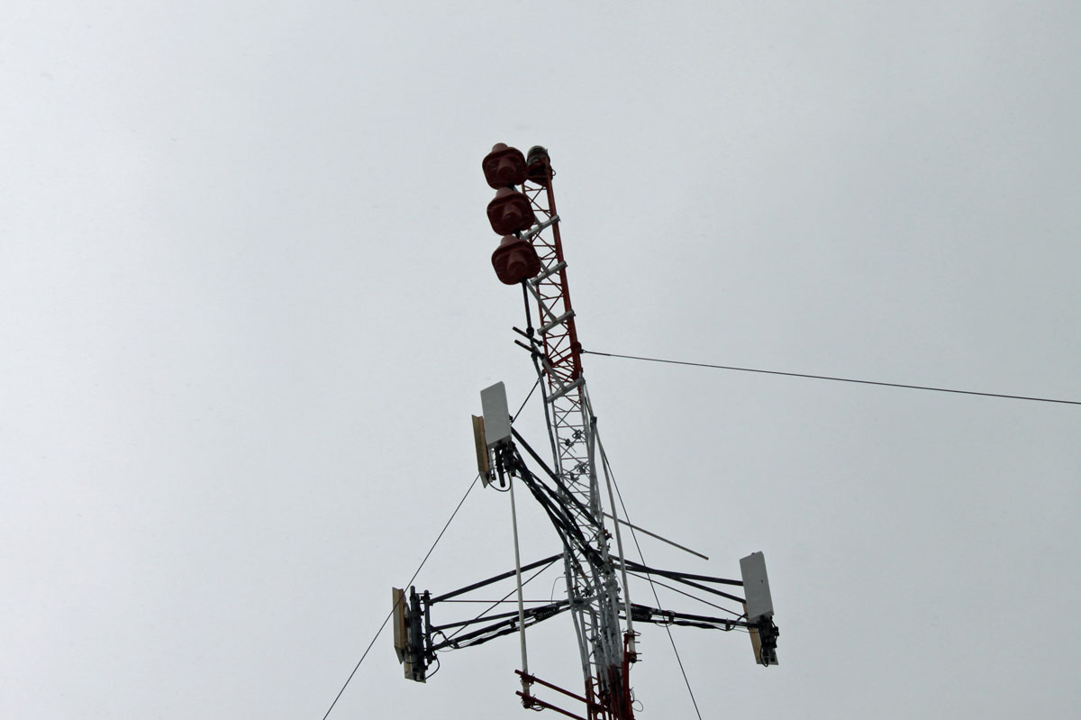
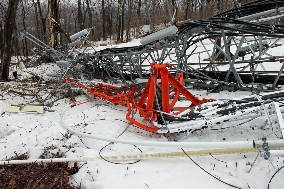
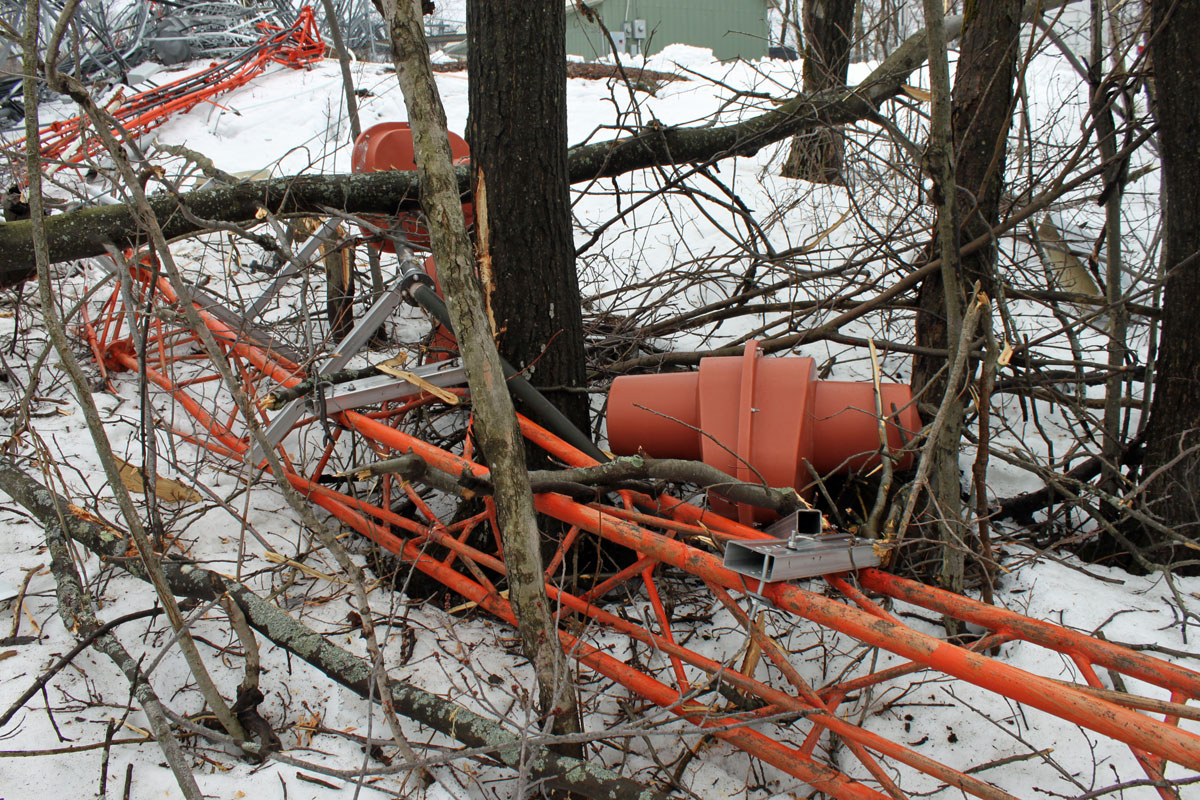
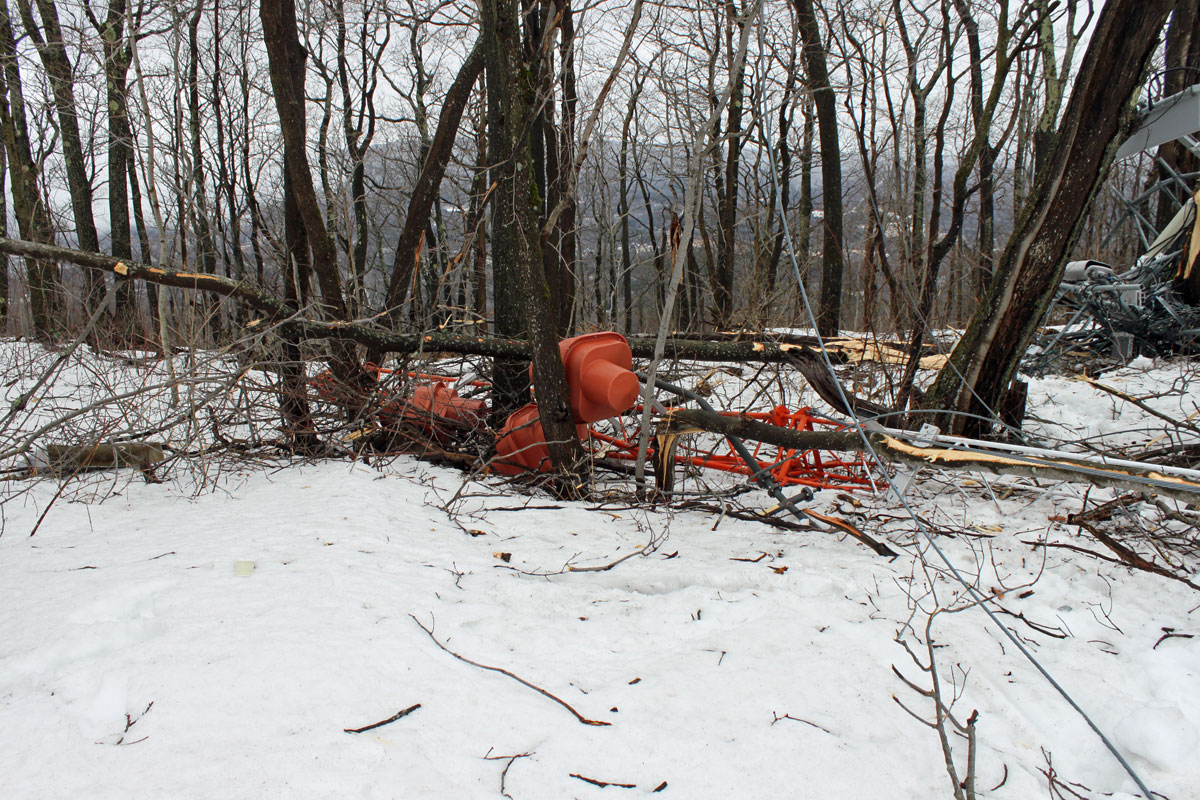
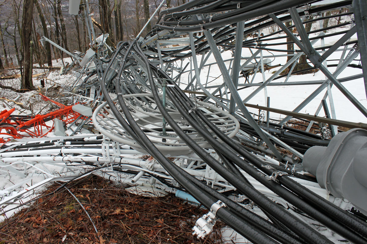
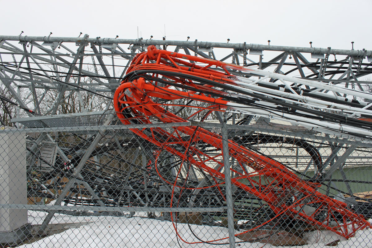
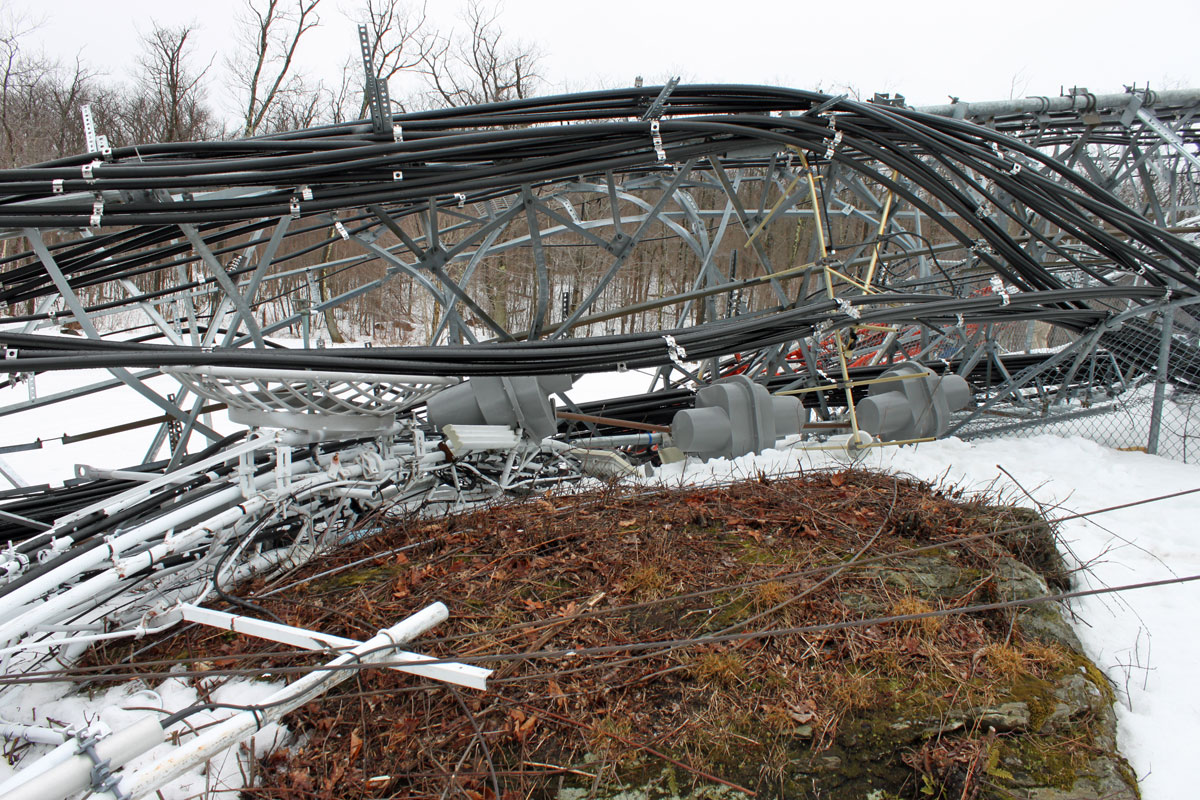
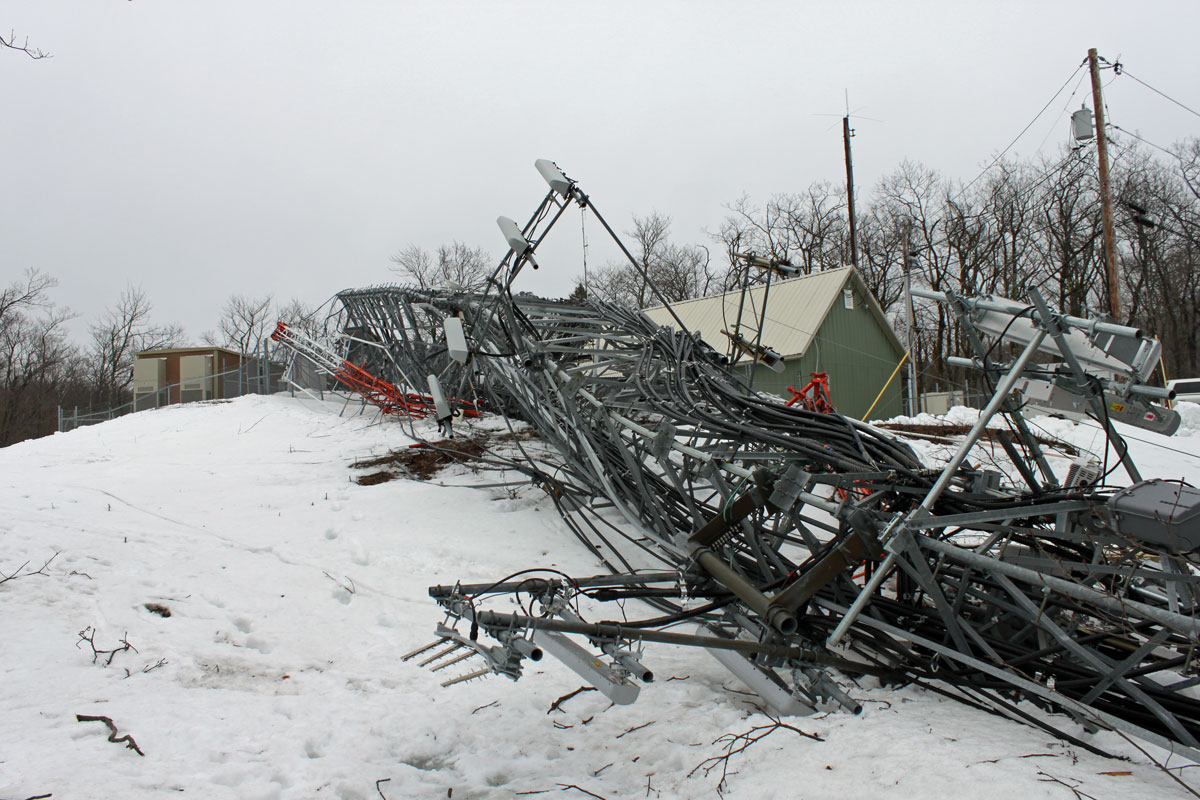
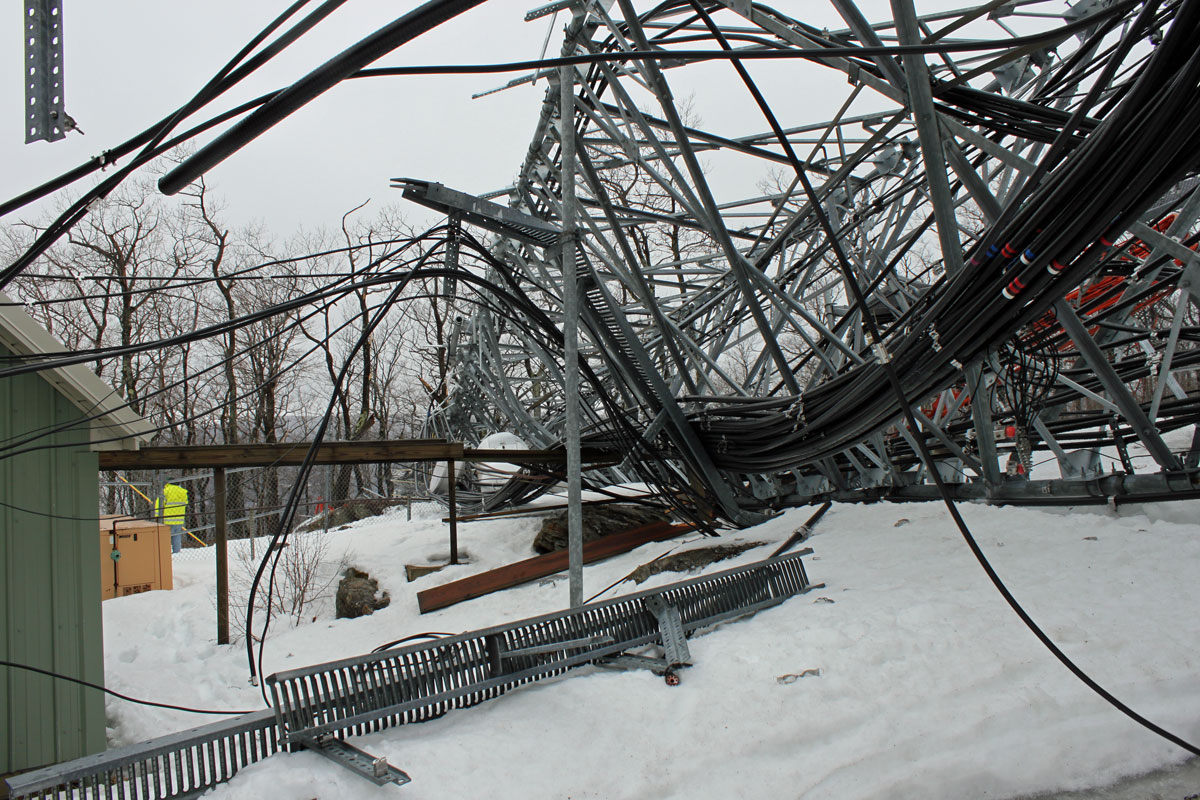
High winds seem to be the culprit in the collapse of two towers in North Adams. According to the Motorola system technicians, it happened at about 12:30 am Sunday morning, which is when all their link loss alarms started going off.  The larger, self-supporting tower broke from its mounting plate and tipped over into the smaller guyed tower next to it. Effected are WUPE-FM and W226AW (WFCR New England Public Radio) as well as NEPR’s new station WNNI which has not officially signed on.

Cellular service for ATT, Verizon, and Sprint/NEXTEL were all knocked offline as well as internet services and E911 dispatch.  Those services are coming back online, with temporary modular cell units en route. N

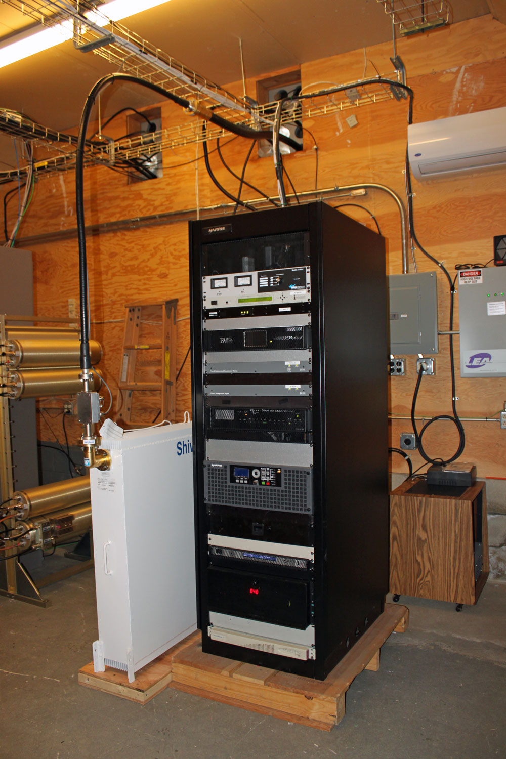
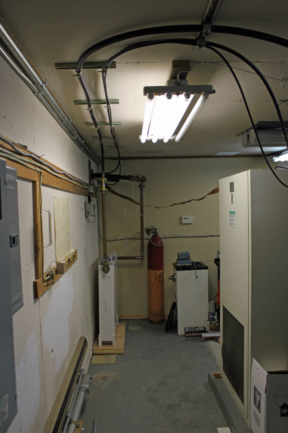
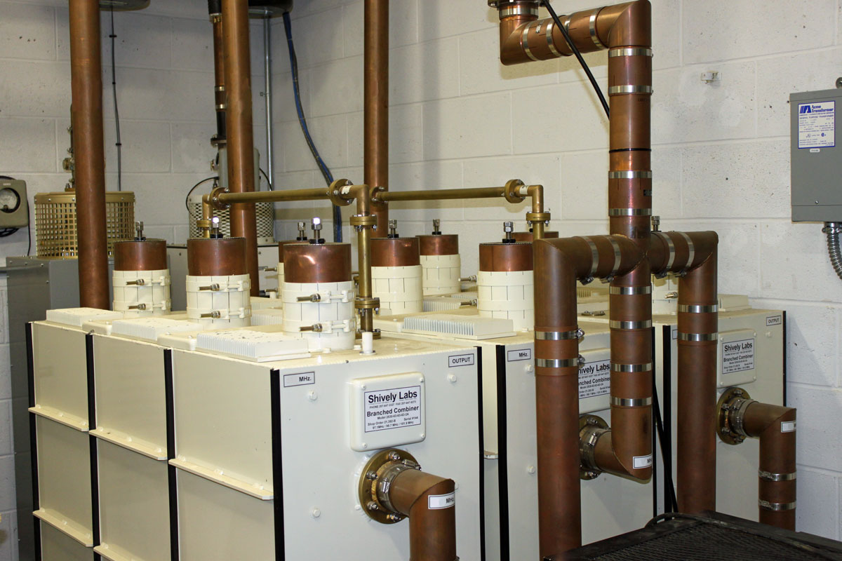
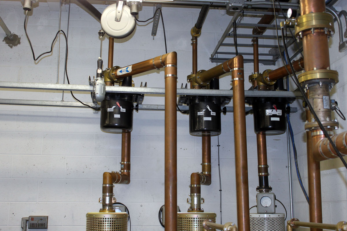
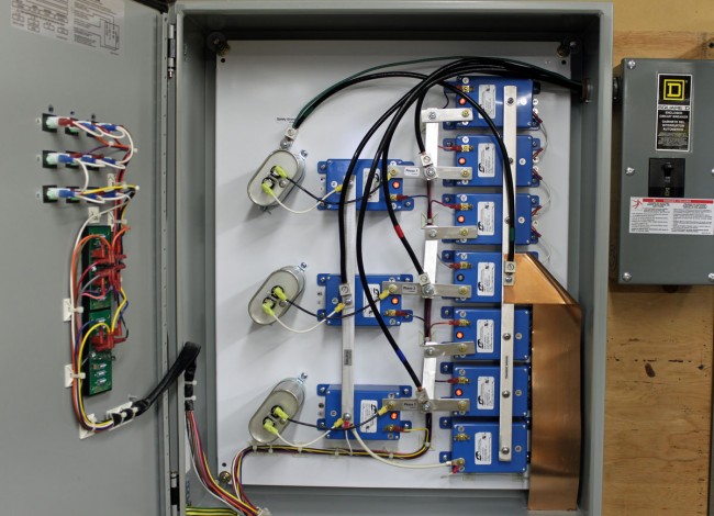
Here are some pictures:

North Adams Cell Tower
WUPE-FM antenna on the ground
WUPE-FM antenna
WUPE-FM antenna
WUPE-FM STL dish
WUPE-FM STL dish
Base of WUPE-FM (formerly WMNB) tower
WNNI antenna
WNNI antenna
WUPE-FM WNNI and W266AW transmitter building
WUPE-FM, WNNI, and W266AW transmitter building
North Adams Cell Tower
Tower base mounting plate, apparent failure point
Tower base mounting plate
Tower Base Mounting Plate

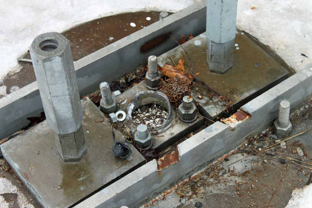
For pictures of the towers during happier times, refer to this post: Filtering for co-located FM transmitters.

Restoration work is underway with WUPE-FM expected to return to the air at low power by Monday afternoon.

Update:

WUPE-FM was returned to air at low power by about 1pm on Monday 3/31.  We took an unused Shively 6812 antenna that was tuned to 94.1 MHz and retuned it to 100.1 by cutting 1/4 inch pieces from the end of the elements until it was on frequency.  It took a bit of doing, but with a network analyzer, we were able to get it to 1.2:1 SWR with symmetrical sidebands.  Running 600 watts, it covers the city of license and then some.

WUPE-FM temporary antenna
WUPE-FM temporary antenna, Shively 6812

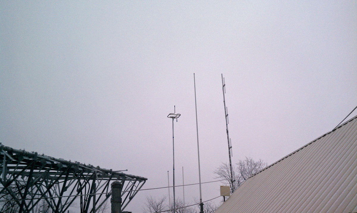
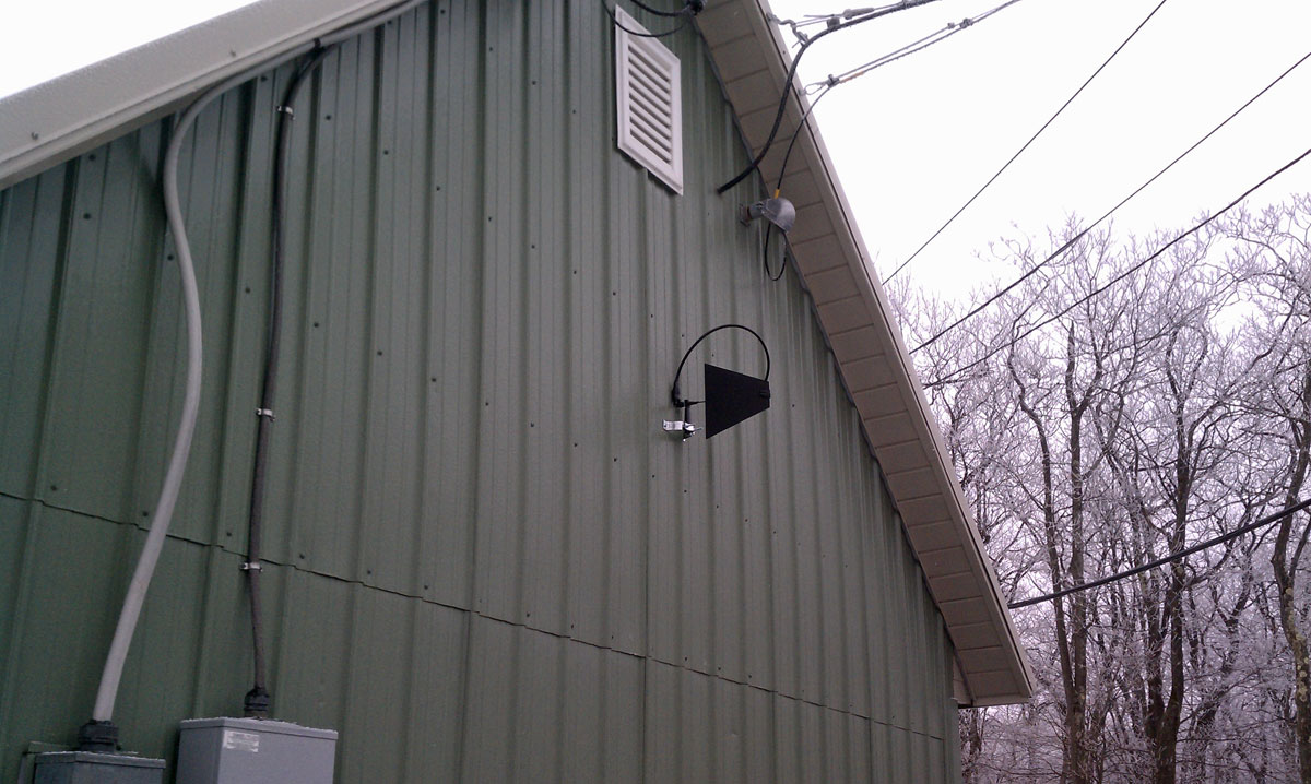
The STL antenna is a survey antenna mounted on the side of the building. In this configuration, with the leaves off of the trees, we are getting about 250 uV signal, which is pretty good.

WUPE-FM temporary STL antenna

The site is now crawling with insurance investigators, cell site technicians, North Adams fire department, Berkshire County Sheriff’s officers, tower workers, etc.  After we finished this work, we cleared out to make more room for everybody else.  Estimated restore time for W266AW is Wednesday 4/2.

Planning for the replacement tower is already in progress, I’d expect it to happen fairly quickly. The next step for the broadcasters is to put up a 70-foot utility pole and get a full-powered antenna for WUPE. This should happen in the next two weeks or so. That will serve as the temporary facility until the new tower is constructed.

Filtering for co-located FM transmitters

Well-sited FM transmitter locations usually want some height above average terrain. This means either a tall tower or a high hill or mountain. Once a site is developed, co-location of other FM transmitters often happens because sites are expensive to develop. A second station can save money by using existing facilities.

For all those newly permitted LPFM stations; pay attention. If you are going to be co-located at an existing FM broadcast site, you may need to do this too.

Interference from intermodulation mixing products can develop when FM transmitting antennas are in close proximity.  This is especially true with solid state, broadband PA commonly used in today’s VHF FM transmitters.  Thus, when antennas are closely placed, external filtering is required.

WUPE FM transmitter site, North Adams, MA

This is the case with a current project in North Adams, Massachusetts.  New England Public Radio is placing WNNI on the air from the WUPE-FM site.  WNNI is using one of those new Harris (now GatesAir?) Flexiva transmitters and WUPE-FM uses a Crown FM-2000A.  The antennas are on separate towers, but the towers are in very close proximity, about 30 feet apart.  In order to avoid any possible problems, a Shively 2602-3A-FB 3 pole filter was installed on each station.  The filter is a bandpass for the station installed and a notch for the other station.

The primary concern here is mixing products between the two transmitters.  Both have broadband solid-state amplifiers with low-pass filters before the output connector.  There are three frequencies of interest;

  1. (F1 – F2) + F1 or (100.1 MHz – 98.9 MHz ) + 100.1 MHz = 101.3 MHz
  2. F2 – (F1 – F2) or 98.9 MHz – (100.1MHz  – 98.9MHz) = 97.3 MHz
  3. F2 + F1 or 100.1 MHz + 98.9 MHz = 199 MHz

That, plus harmonic measurements out to three or four harmonics of the fundamental frequency should be enough to demonstrate compliance with FCC out-of-band emissions standards.

Measurements on these frequencies must meet the emissions standards outlined in FCC 73.317 (d), which states:

Any emission appearing on a frequency removed from the carrier by more than 600 kHz must be attenuated at least 43 + 10 Log10 (Power, in watts) dB below the level of the unmodulated carrier, or 80 dB, whichever is the lesser attenuation.

It is also noted that this site has several cellular carriers and no doubt has or will have LTE at some point. We all know that rural LTE installations can create self-induced problems, which are then conveniently blamed on the nearest broadcast station because, hey, why not?

To further complicate matters, New England Public Radio also has a translator, W266AW (101.1 MHz) on the same tower as WNNI.  The same measurements noted above must be repeated for the translator.

WNNI FM transmitter and Shively filter

WNNI equipment rack.  This is one of those new Harris (GatesAir?) Flexiva FM transmitters.

WUPE-FM Shively Filter

WUPE FM filter installation

wave spaced Shively antenna.  Antenna for W266AW below
WNNI 4 bay half wave spaced Shively antenna. Antenna for W266AW below

New WNNI antenna mounted on cell tower next to WUPE-FM tower. The W266AW translator antenna is directly below WNNI’s main antenna.

WUPE-FM 3 bay half wave spaced Shively antenna

WUPE-FM antenna installed on the original broadcast tower.  I believe the tower dates from 1959 or so.

It is important to get this type of installation right the first time.  Creating interference all around or above the FM band is never a good strategy.  Going back to ask for more funds to make something right is also highly frowned upon.

The Shively Branched combiner

Did some work a while ago at a transmitter site that had three transmitters combined into one antenna.  The site uses a Shively branched combiner:

Shively Branched combiner

Each transmitter can be tested into a separate 20 KW dummy load:

Three inch coax switches

Transmitter themselves are Nautel NV15s:

Nautel NV20 transmiters
Nautel NV15 transmiters

Except for the one on end, which is an older BE FM20A.

Series surge suppressor

Radio facilities, particularly mountaintop transmitter sites, are prone to power transients. The causes can be varied, but most often, lightning is the culprit.  Long power transmission lines to the site are vulnerable to direct strikes and EMF-induced spikes from nearby strikes.  Other issues, such as switching transients, load fluctuations, and malfunctioning equipment can lead “clear weather” outages.  Of course, the best way to deal with such things is through prevention.

Power line surge suppressors have been around for quite some time.  They usually take the form of a MOV (Metal Oxide Varistor) connected between the hot leg and neutral or ground.  There are a few differences in designs, however.  Typically, most facilities employ a parallel surge suppressor.  That normally takes to form of an enclosure hung next to the main power panel with a group of MOV modules in it.  The MOVs are fed from a circuit breaker in the panel.  Like this:

LEA parallel surge suppressor
LEA parallel or shunt surge suppressor

This is an LEA three-phase 208-volt shunt surge suppression unit, which has MOVs between all phases to ground and each other.  That is connected in parallel to the electrical service with the circuit breaker disconnect.  These function well enough, provided there is a good bit of series inductance before the unit and also, preferably after.  The series inductance can come from many sources, including long secondary leads from the utility company transformer or electrical conductors enclosed in metal conduit, particularly rigid (verses EMT, or FMC) metal conduit.  The inductance adds a bit of resistance to the transient voltages, which come in higher than 50 or 60 Hz AC waveform.

A better method of transient protection is the Series Surge Suppressor.  These units are installed in line with the incoming service and include an inductor to add the required series resistance coupled with MOVs and capacitors.  Most series surge suppressors also filter out harmonics and RF by design, something desirable, particularly at a transmitter site.  Series surge suppressors look like this:

LEA DYNA systems series surge protector

This is an LEA three-phase 240-volt unit.  As in the other example, all phases have MOVs to neutral and each other.   There are MOVs and capacitors on the line and load side of this unit (the line side is the bottom of the inductor).  A basic schematic looks like this:

Series surge suppressor basic schematic

A few things to note; MOVs have a short circuit failure mode and must be fused to protect the incoming line from shorts to the ground.  MOVs also deteriorate with age, the more they fire, the lower the breakdown voltage becomes.  Eventually, they will begin to conduct current at all times and heat up, thus they should also be thermally fused.  MOVs that are not properly protected from overcurrent or over-temperature conditions have the alarming capacity to explode and/or catch on fire.  From experience, this is something to be avoided.  Matched MOVs can be paralleled to increase current handling capacity.

The inductor is in the 100 µH range, which adds almost no inductive reactance at 60 Hz.  However, it becomes more resistive as the frequency goes up.  Most transients, especially lightning, happen at many times the 60 Hz fundamental frequency used in power distribution (50 Hz elsewhere unless airborne, then it may be 400 Hz).

Capacitors are in the 1-10 mF range and rated for 1 KV or greater as a safety factor.  The net effect of adding capacitance is to create a low-pass filter.  Hypothetically speaking, of course, playing around with the capacitance values may net a better lowpass filter.  For example, at 100 uH and 5 mF, the cutoff frequency is 225 Hz, or below the fourth harmonic.  Care must be taken not to affect or distort the 60 Hz waveform or all sorts of bad things will happen, especially to switching power supplies.

These units also need to have a bypass method installed.  If one of the MOV modules needs to be replaced, power to the unit has to be secured.  This can be done by connecting it to the AC mains before any generator transfer switch.  That way, the main power can be secured and the site can run on generator power while the maintenance on the surge suppression unit is taking place.