The rotary phase maker

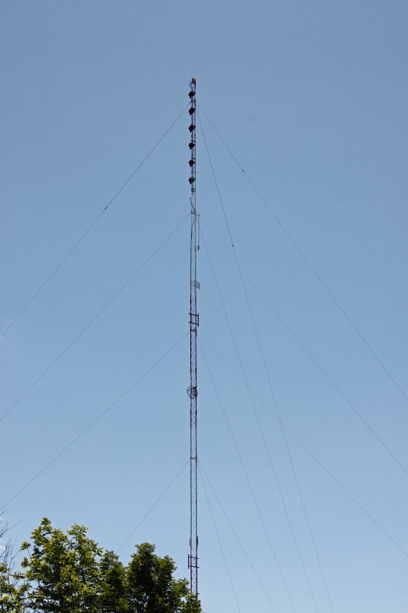
I alluded to this in an earlier post: Open Delta three phase service.  Some transmitter sites are fairly remote and three-phase power is not available.  Occasionally, with lower-powered radio stations, this is acceptable because those transmitters can be configured to run on single-phase power.  However, almost any transmitter above five kilowatts or so will require three-phase power.  This is the case at the WQBJ transmitter site in Palatine Bridge, NY.  The site is located in the middle of farmland and only has single-phase service.  The nearest three-phase service is several miles away and the utility company wants several hundred thousand dollars to upgrade the line.

WQBJ transmitter site electrical service

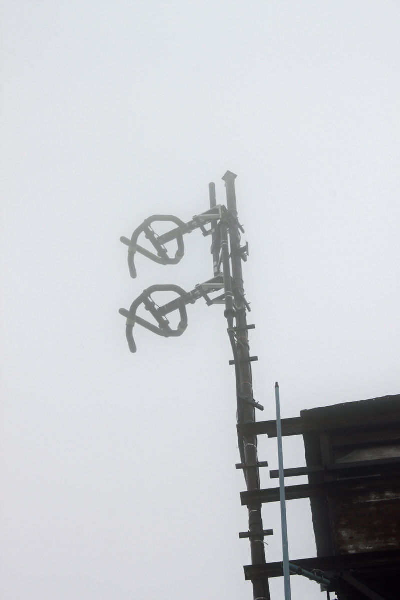
The station is a class B FM with a six-bay full wave-spaced antenna.  Even so, the TPO is 17 KW, which makes some type of three-phase service a requirement.

WQBJ six bay Shively 6810 antenna
WQBJ six-bay Shively 6810 antenna

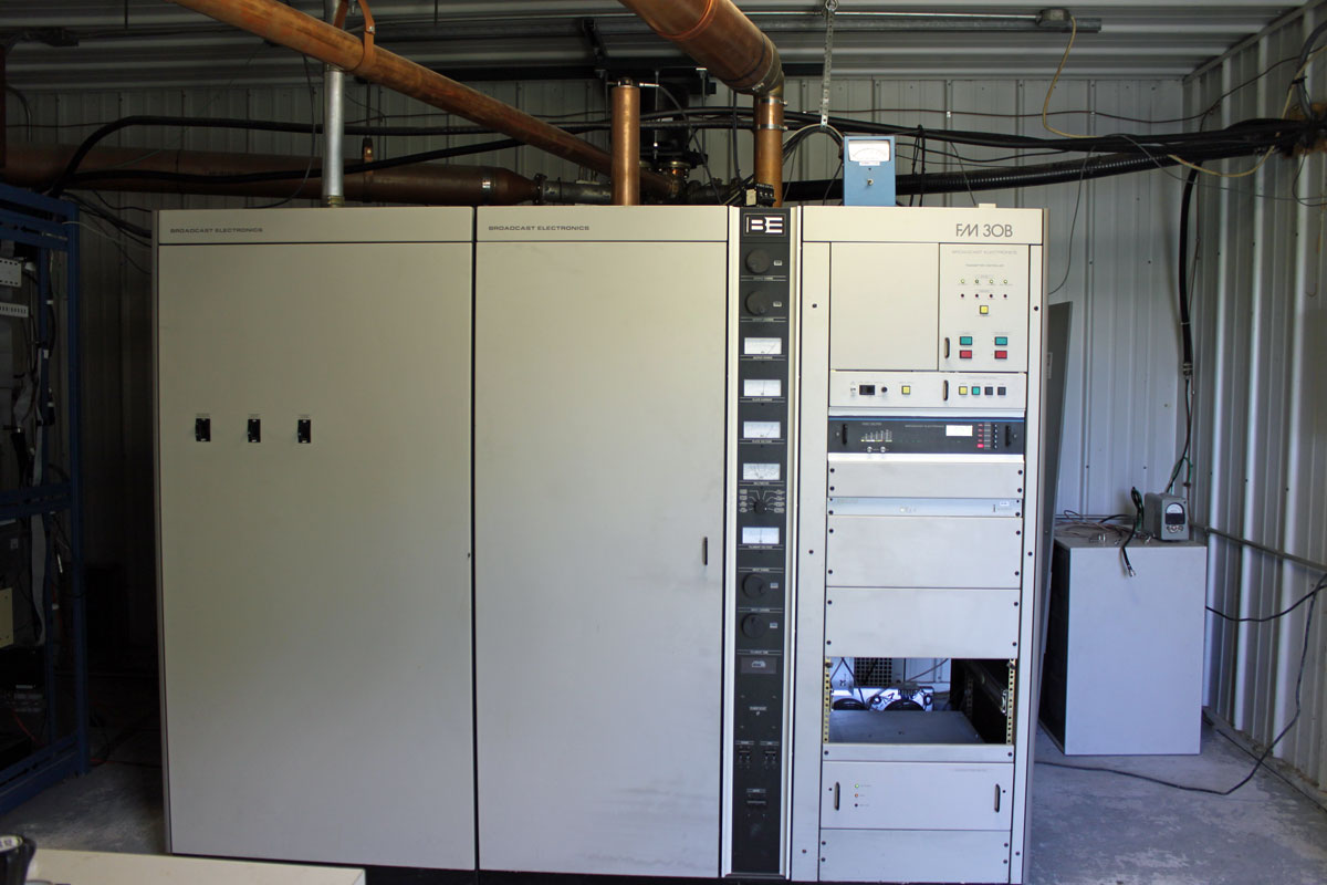
The main transmitter is a Broadcast Electronics FM30B, which is now 25 years old.

WQBJ main transmitter, Broadcast Electronics FM30B

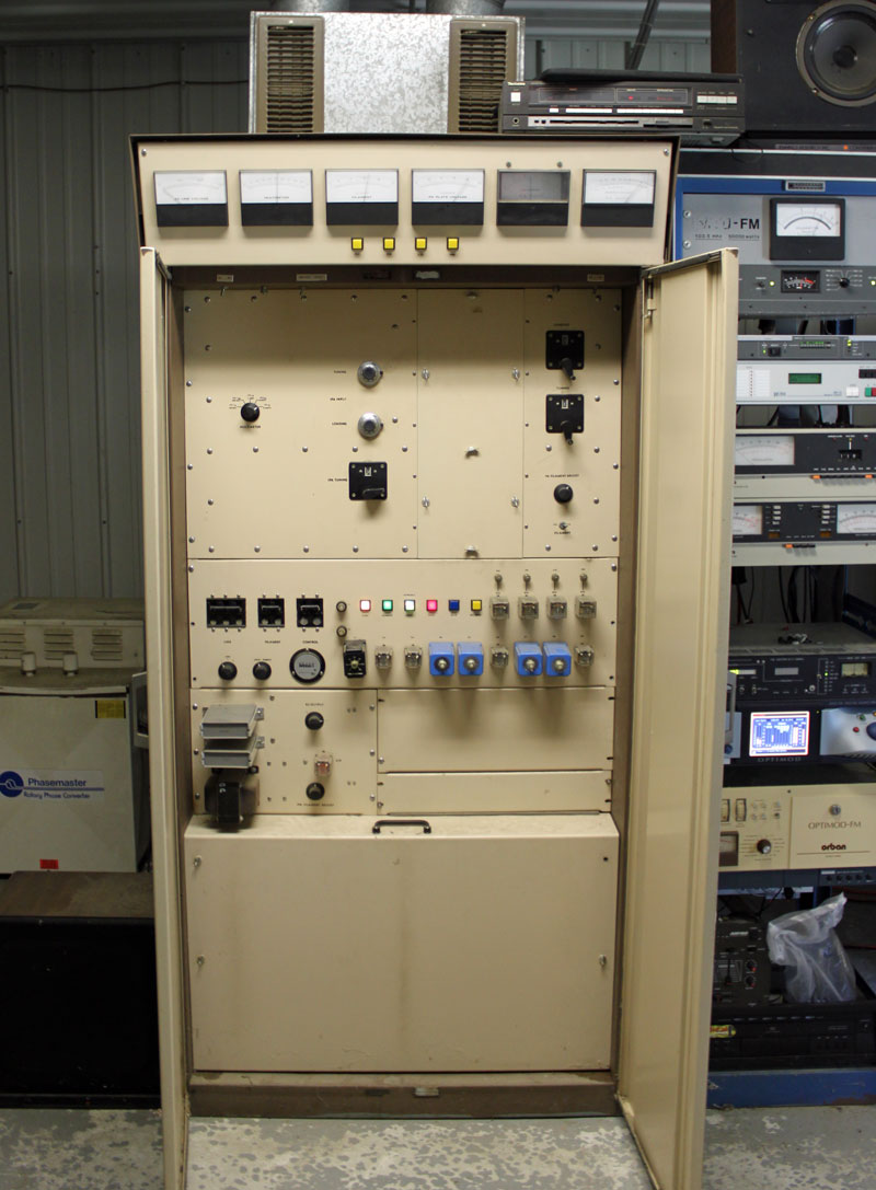
The backup transmitter is a CSI FM20T, which is almost forty years old.

WQBJ backup transmitter, CSI FM20T

Rather than do an open delta service, which is not desirable for several reasons, both transmitters have their own rotary phase makers.  From a reliability and redundancy standpoint, this is the right way to equip this site.  The rotary phase makers are essentially a motor generator combination which takes the split phase power and generates a third phase.

WQBJ phasemaster, backup three phase converter
WQBJ Phasemaster type T, backup three-phase converter
Phasemaster parallel connection diagram

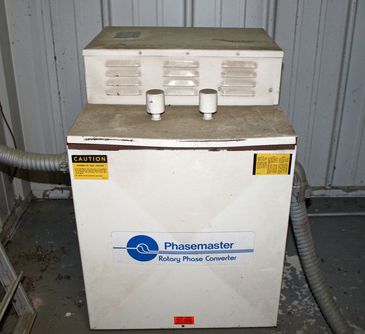
The phasemaster is is a 40 KVA unit and is connected to the backup CSI transmitter

WQBJ Roto Phase, main three phase rotary converter
WQBJ ARCO Roto Phase, main three-phase rotary converter

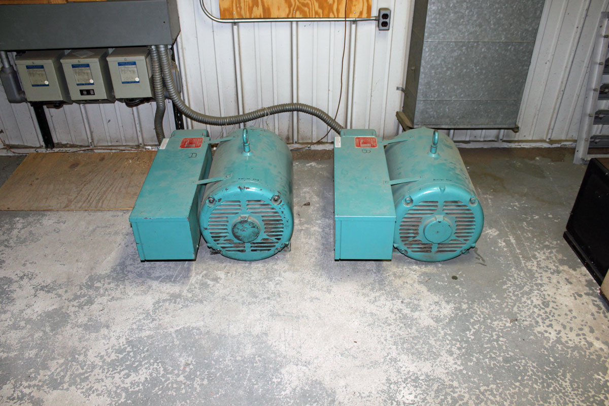
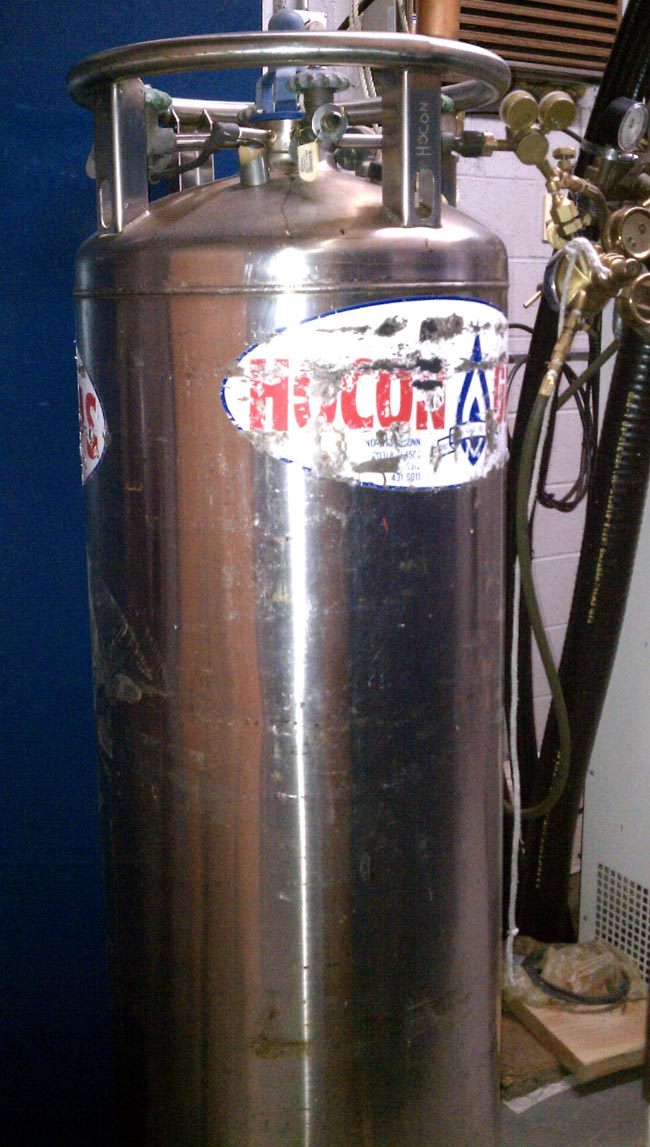
The Roto Phase unit for the main transmitter is actually two 40 KVA units connected in parallel through dry core isolation transformers.  Incidentally, the Roto Phase units need to have their bearings changed every ten years or so.  This requires the units be disconnected, placed up on their end.  To get the old bearing out, the housing has to be cooled with liquid CO2.  Both units are due for new bearings soon, which should be a pleasant job indeed.

Repairing the Nautel VS2.5 transmitter

The newish Nautel VS2.5 transmitter installed at WJJR had an RF module failure. This particular model transmitter does not have slide-in RF modules as other Nautel transmitters do.  To fix this transmitter, it has to be pulled out of the rack, flipped over, and opened from the bottom. The module replacement is very straightforward, there are five solder pads that connect to wires carrying the input, output, power supply, and bias voltages.

Nautel VS2.5 transmitter RF modules and combiner

The troubleshooting guide gives good instructions on how to check the PA MOSFETS with a DVM. I found that 1/2 of the device in PA1 was bad:

Schematic Diagram, NAPA31

All in all, not a very hard repair. This was under warranty, so a replacement RF pallet was sent to the station without charge. The problem is more about where the transmitter is located:

Killington Mountain, Killington, VT

Killington Peak is the second tallest mountain in Vermont, topping out at 4,235 feet (1,291 meters). In the winter, one can take the chair lift to the top. In the summer, the road is drivable with a four-wheel drive. In those in between months, access to the top can be very tricky at best. We had a pretty wet spring this year, so the roads up the mountain are just now becoming passable for vehicles.

Even after reaching the parking lot, there is still a 10 minute walk to the peak, another 200 or so feet up a steep, rocky trail.

Further complicating things, this transmitter is wedged into this little shack, which holds; a BE FM3.5A transmitter (defunct WJJR), a Harris HT3 transmitter (WZRT), an ERI combiner, two racks of equipment (STLs, Exciters, remote controls, etc) a backup QEI transmitter, an Onan generator transfer switch:

Killington Peak fire tower, WJJR WZRT transmitter building

Both stations run into this ERI half-wave spaced antenna:

WJJR WZRT ERI antenna

It is very tight in this transmitter room. There is a new tower on Killington Peak, which is still under construction. At some point, the plan is to move into the larger building next to the new tower.

Killington Peak tower

On a clear day, the view from the top is spectacular. On this day, the peak was in the clouds, so not so much:

Killington Peak view

It is a great site, the HAAT is 2590 feet (790 meters) and the stations carry forever on relatively low power outputs.

North Adams tower update

As promised in an earlier post, here is an update on the progress at the North Adams tower site for the restoration work on WUPE-FM and WNNI. For those unfamiliar, refer to this post: North Adams Tower Collapse.

A contractor installed a 70-foot wooden utility pole last week.  We ordered new Shively Versa2une FM antennas as replacements for the antennas destroyed when the tower fell last March.  These new antennas are field tunable, which is a nice feature.  The idea is that this pole will be used until the replacement tower is constructed, which is many months away.  After the new tower is up, I would like to keep the pole in place as a backup facility for both stations.

North Adams restoration work

The bucket truck arrived but the driver had a bit of bad news; there is room for only one person in the bucket. The boss pipes up and says “Oh, that’s okay, Paul can go up and run the bucket”

WAT!

Are you sure this is a good idea?

So anyway, it turns out running a bucket truck is not a huge deal; there is a joy stick of sorts that moves the booms around, up down, sideways, etc. Once you get the feel for it, it is pretty easy and three dimensional movement becomes second nature.  That being said, at 70 feet in the air, everything gets a little wobbly, so it is best not to jerk the controls around.

The antennas were mounted on a 2 inch pipe which was attached to the pole with 1/2 inch threaded rod. We left a little bit of pipe sticking up above the top of the pole to get the FM antennas as high as possible.

Mounting pole to tower
Mounting pole to the tower
Some dude in a hang glider checking out the work

Getting photobombed by some guy in a hang glider is a new experience.  No day is exactly like another in this line of work.

WUPE and WNNI temporary antennas
WUPE-FM and WNNI temporary antennas

The antennas were tuned up once they were up on the pole. We did this with the network analyzer, which made the job very easy. WUPE-FM (top antenna) started using this antenna on Wednesday afternoon (5/7) with greatly increased power output.   This gets the station almost the same coverage area as they had before the tower collapse.  We tested WNNI (bottom antenna) and it all looked good. WNNI is still waiting for a temporary wireless internet feed for program delivery. Once that is established, we will have to do the intermod measurements one more time before they can go on the air.

Here are some pictures of the cleaned-up site:

North Adams, fallen tower removed

The temporary monopole being used by the cell providers:

North Adams temporary cell tower

Basically the pole is ballasted in place by those huge concrete blocks.

WEBE pictures

WEBE is fairly unique in that its antenna is mounted on the side of a 500-foot smoke stack. I took a few pictures last winter:

WEBE Main antenna
WEBE Main antenna

This is a close-up of the Antenna:

WEBE main antenna, Shively 6 bay half wave spaced
WEBE main antenna, Shively 6 bay half wave spaced, ERP 50 KW

Here is an even closer view from a different angle:

WEBE main antenna, courtesy of NECRAT

From this angle, one can see the mounting brackets and the wire mesh reflector installed on the smoke stack.  From the first picture, one can see that the 400 MW PSEG coal fired power plant puts out a lot of combustion products when on line.  Combustion is an exothermic chemical reaction that looks like this:

Hydrocarbon Fuel + Oxidizer + Nitrogen  → Heat + CO2 + H2O + NOx

Included in this are any trace elements that are found naturally in the coal that is being burned.  These include things like Mercury, Nickel, Uranium, et cetera.  These trace elements can concentrate around the smoke stack because they fall out of the particulate quickly and these plants burn a lot of coal.  The above picture was taken on a very cold day, most of what is coming out of the smoke stack is steam.

The issue for the radio station is when the particulate matter accumulates on the antenna, effectively shorting it out.  The solution was to place the RADOMES around the elements and then constantly purge the RADOMES with nitrogen.  Thus, this liquid N2 tank is vital for the operation of the radio station:

Liquid Nitrogen Tank

Each element of the antenna has a small hole in the feed line. N2 is fed continuously into the transmission line at a pressure of about 1.5 inches water column which then purges the RADOMES keeping any combustion products out of the RADOMES.  The N2 tank needs to be changed out every 18-21 days and weights over 650 pounds when full.