Co-located common antenna FM stations

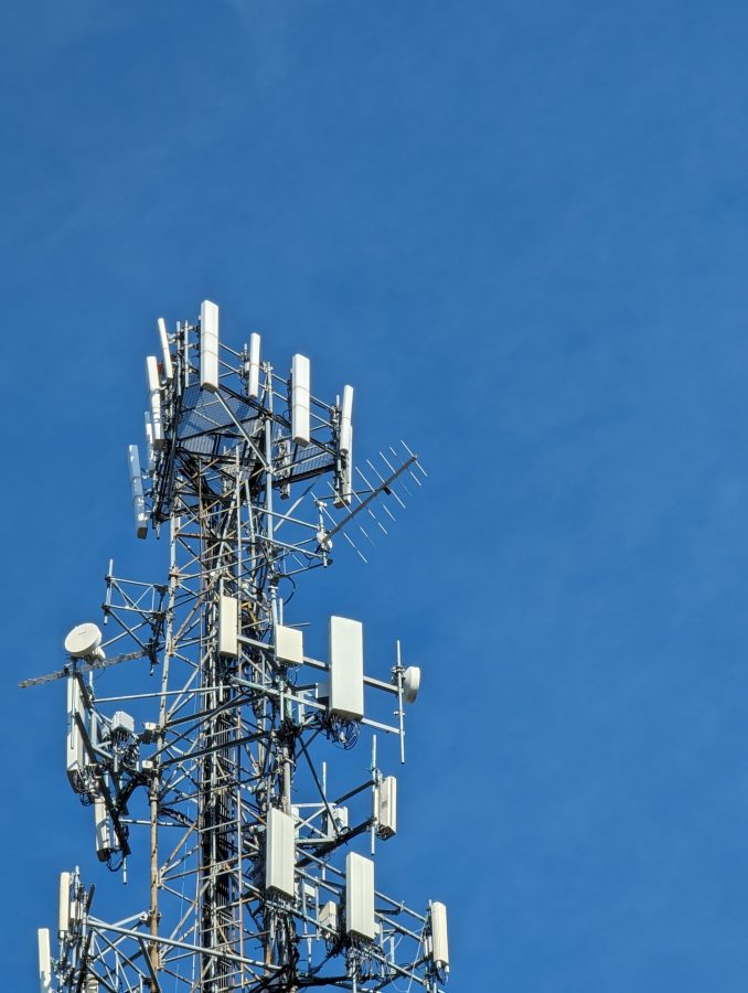
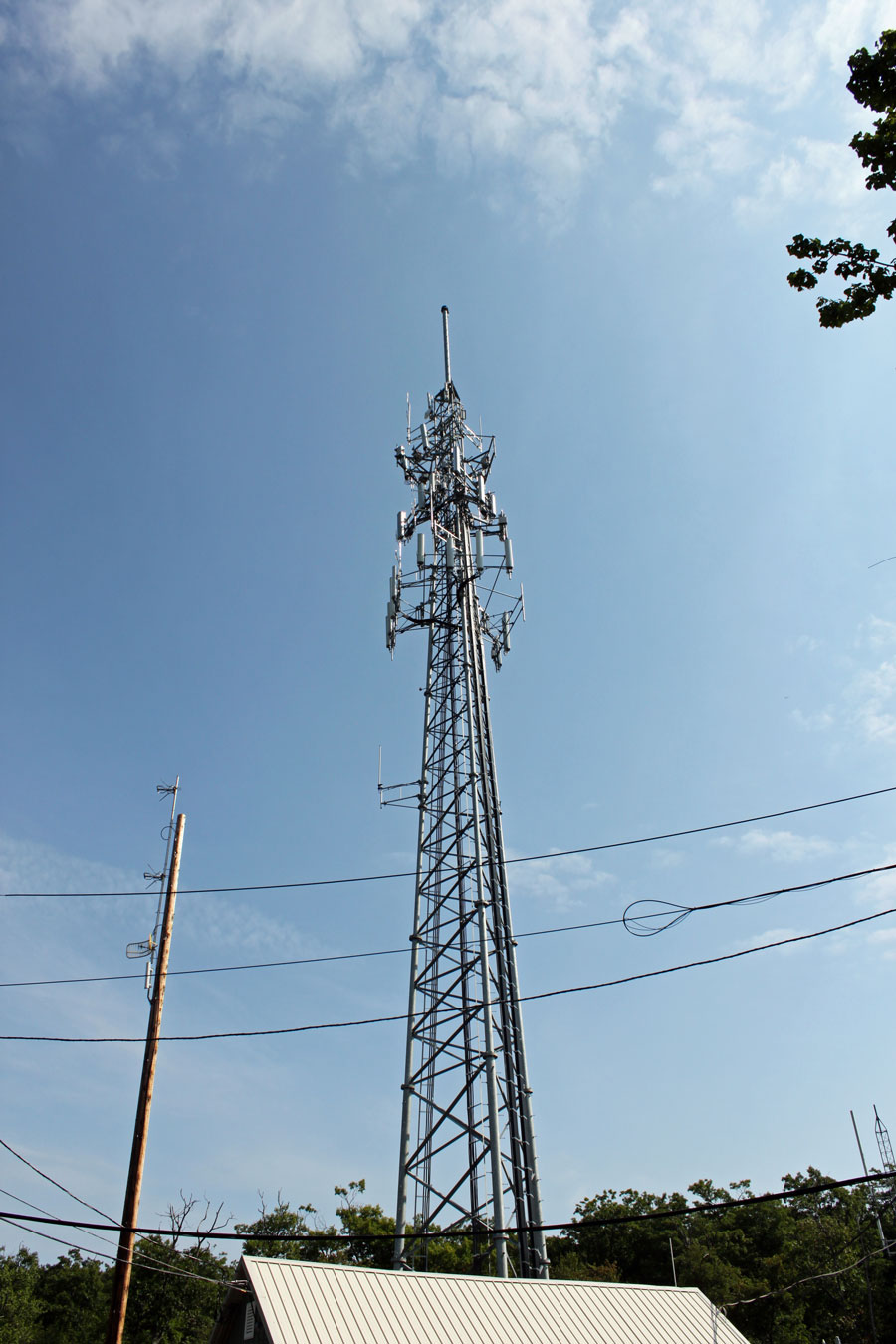
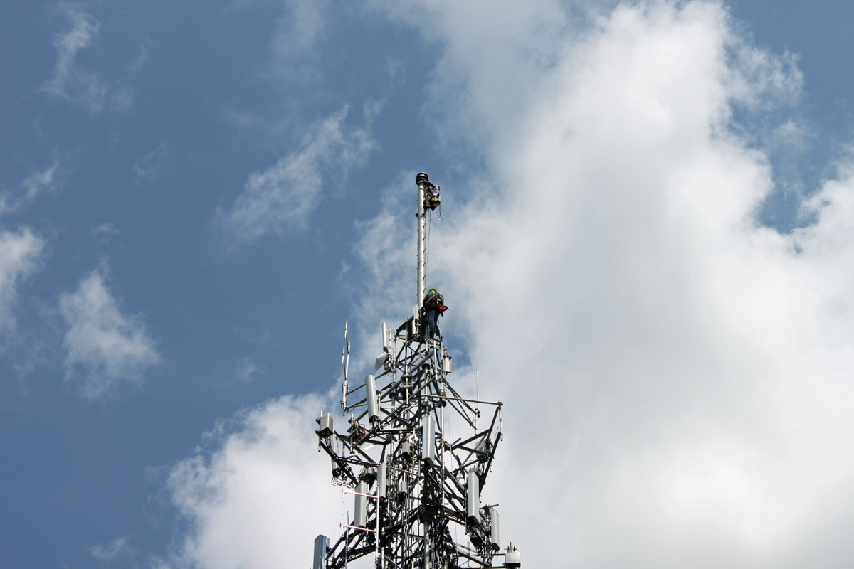
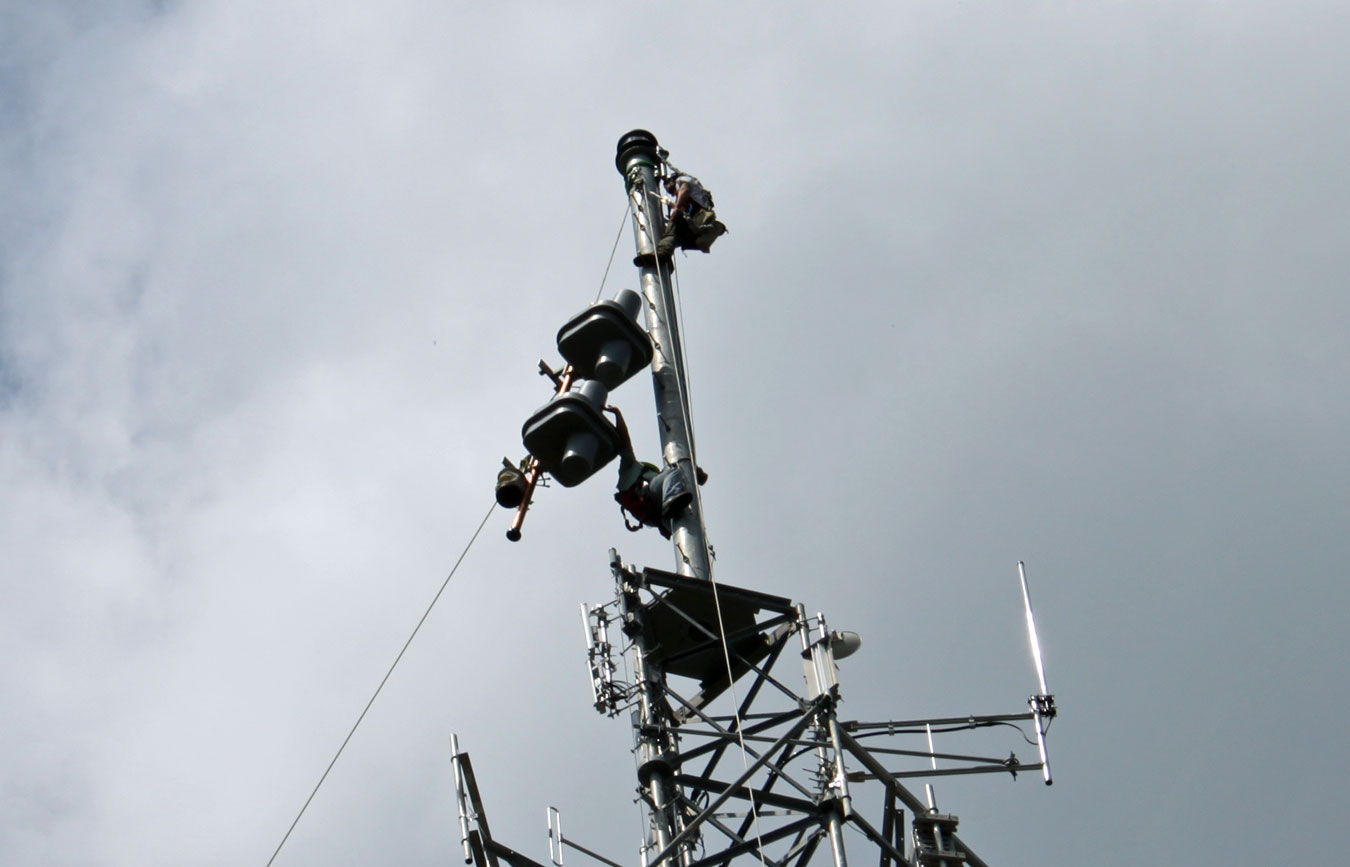
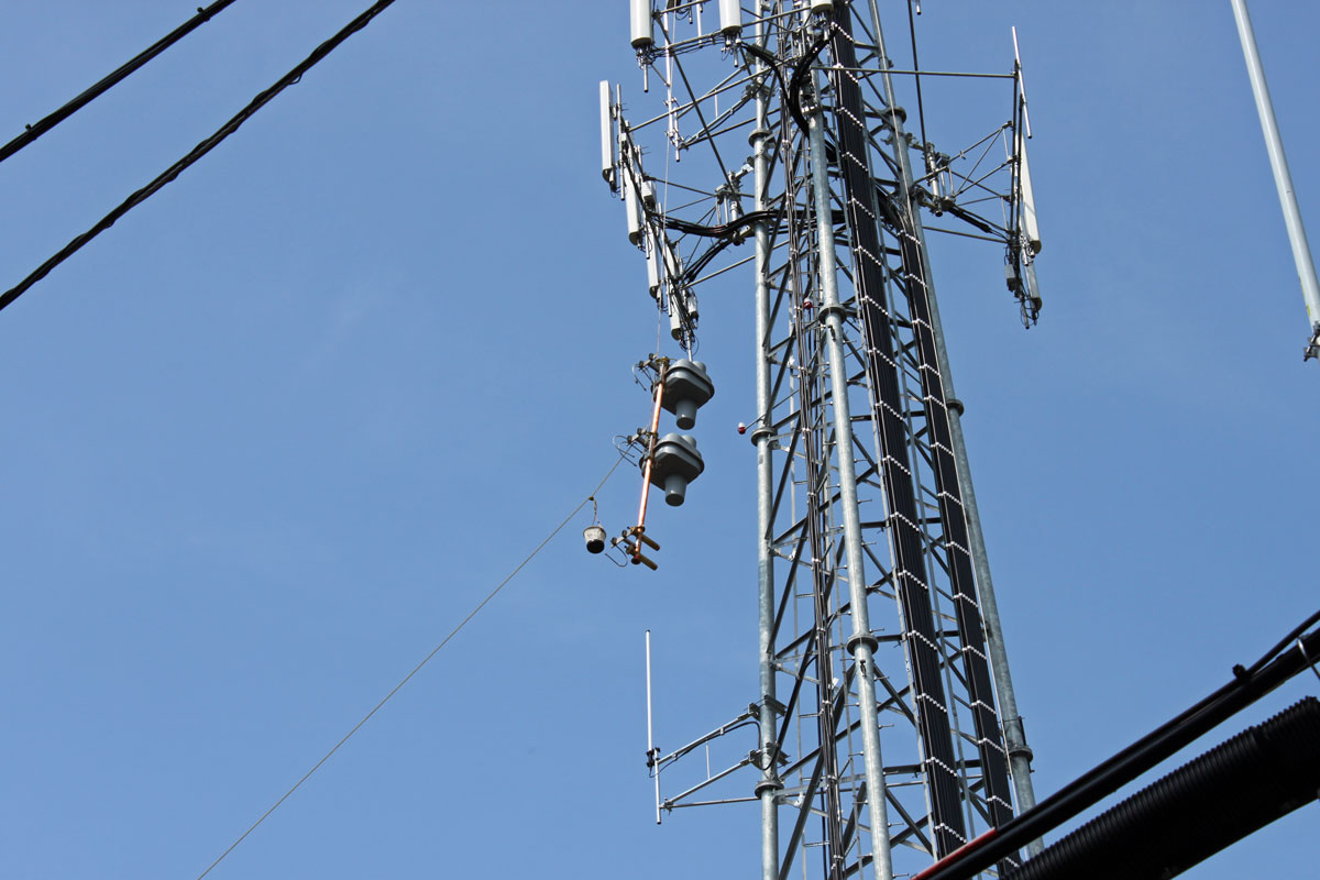
One of our clients needs to move to another transmitter site because their lease is expiring at the old site. We have been working on this for several months now. One of the nice features of this project is the panel antenna.

Kathrein 754154 spec sheet

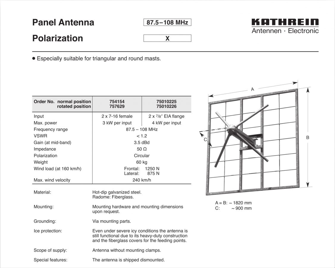
This is installed in a 2-bay 3-around configuration. I don’t see this particular model in the Kathrein catalog anymore, but there are other cross-polarized panel antennas available from them.

Colocated tower

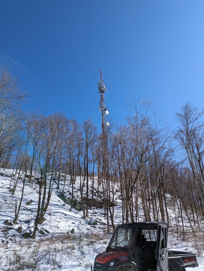
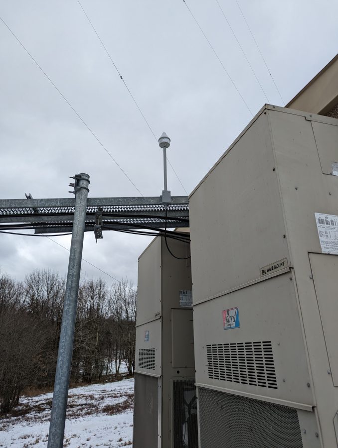
There are many existing services on this tower including two full-power FM stations, a translator, a VHF TV station, numerous cell carriers, etc. Once the installation is done we will have to check carefully for intermodulation.

Honda Track Machine

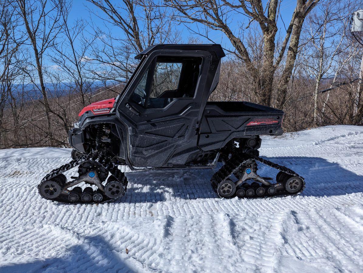
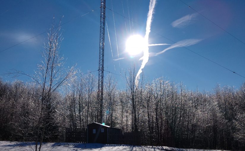
Winter in the Northeast; there was just enough snow and slush on the access road that the truck could not make it to the top of the hill. This track machine works great. We have added a Polaris Ranger 900 to our inventory (not this machine) for winter access to several of the more difficult transmitter sites. While I do enjoy the occasional walk in the snow, the key word here is occasional.

AAT branch combiner inputs

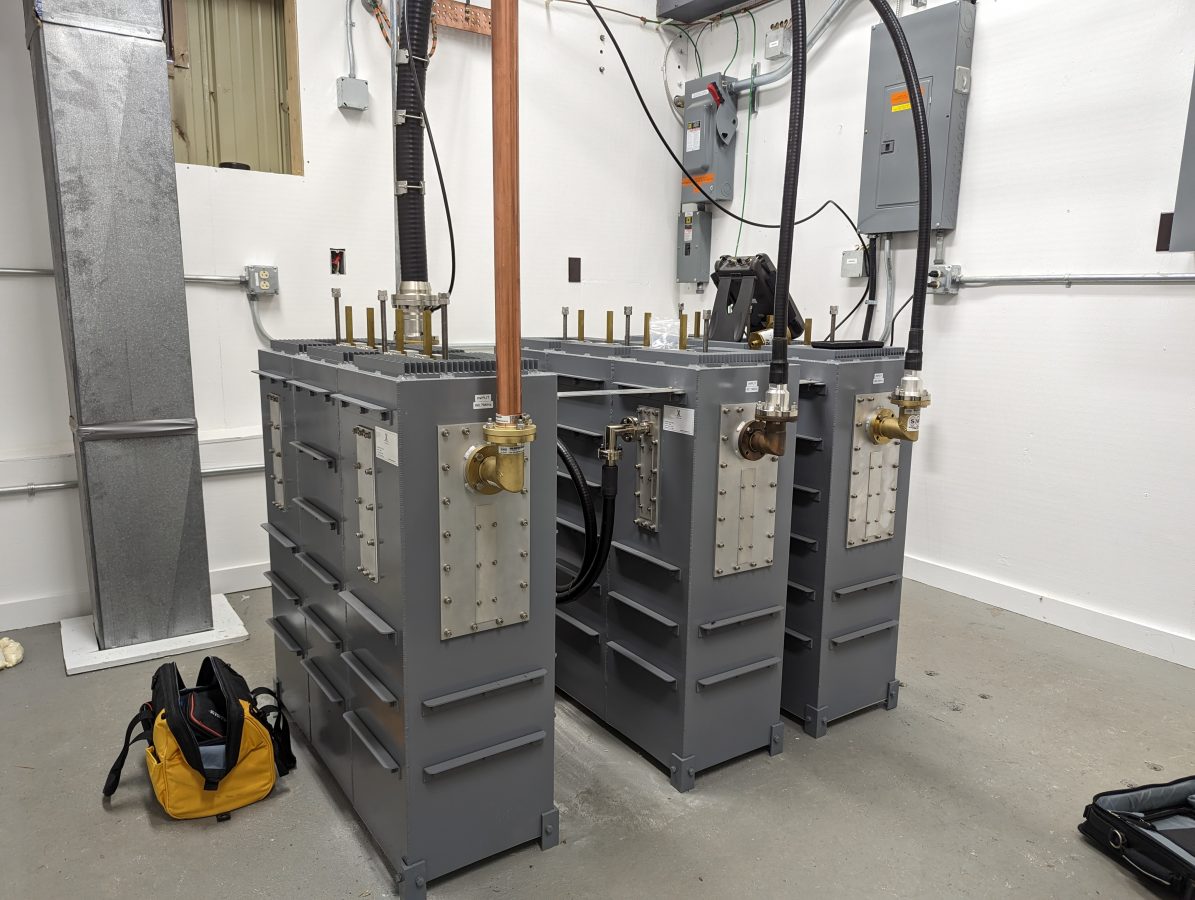
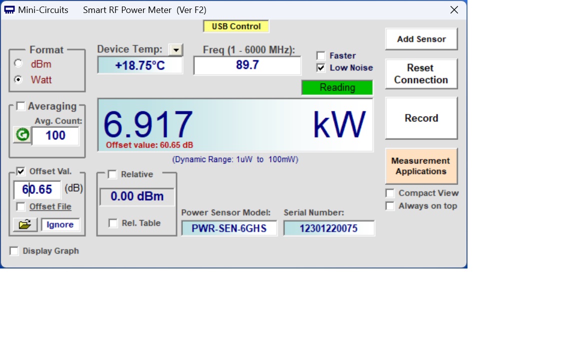
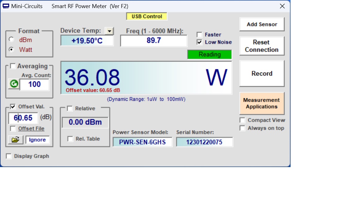
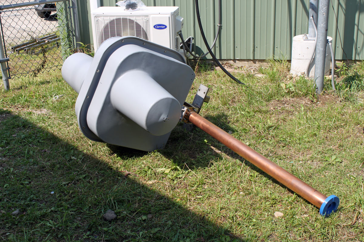
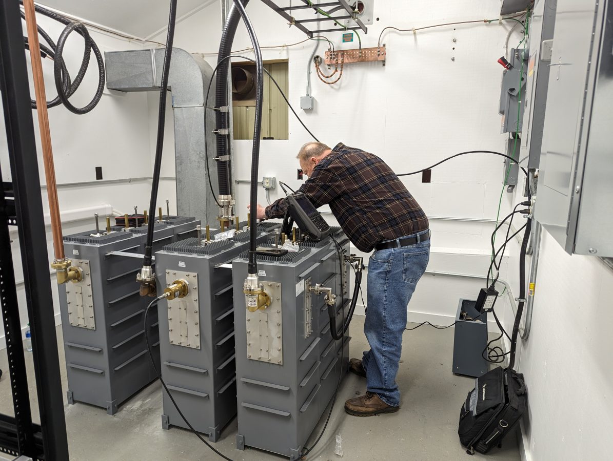
The three stations are combined into the panel antenna with this rather nice American Amplifier Technologies C-IR-3-3-30K-N branch combiner.

AAT branch combiner output side

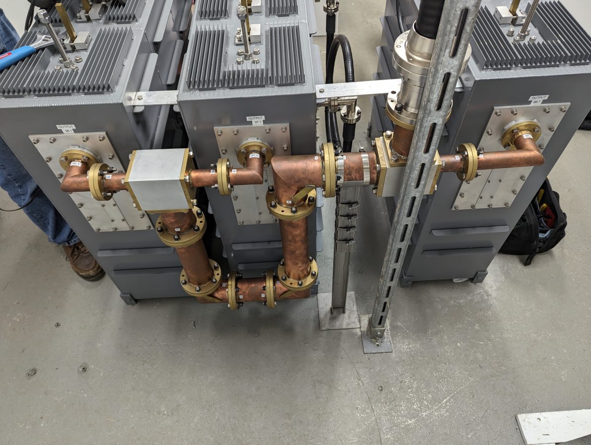
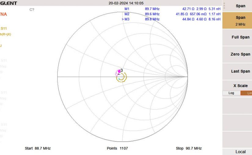
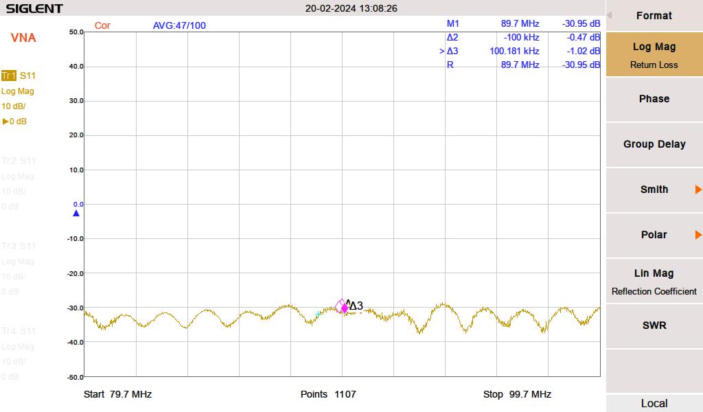
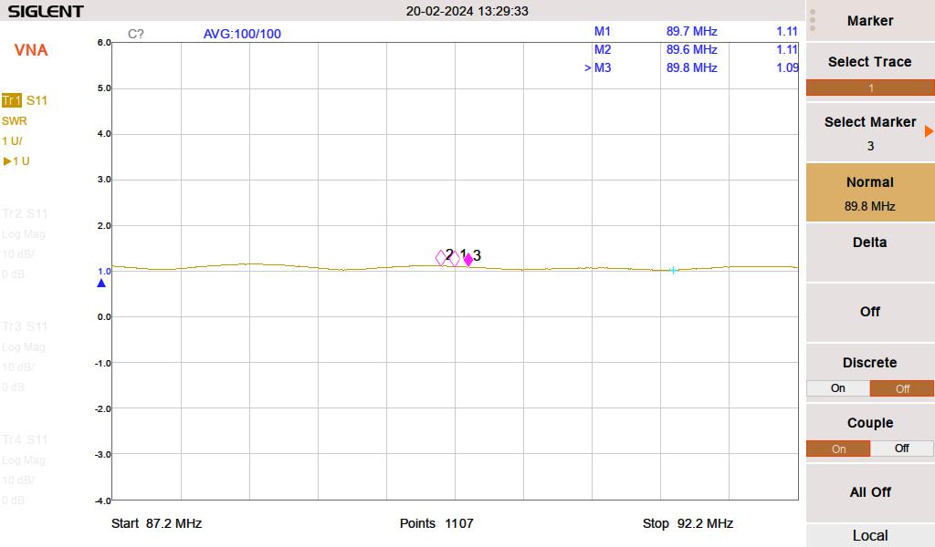
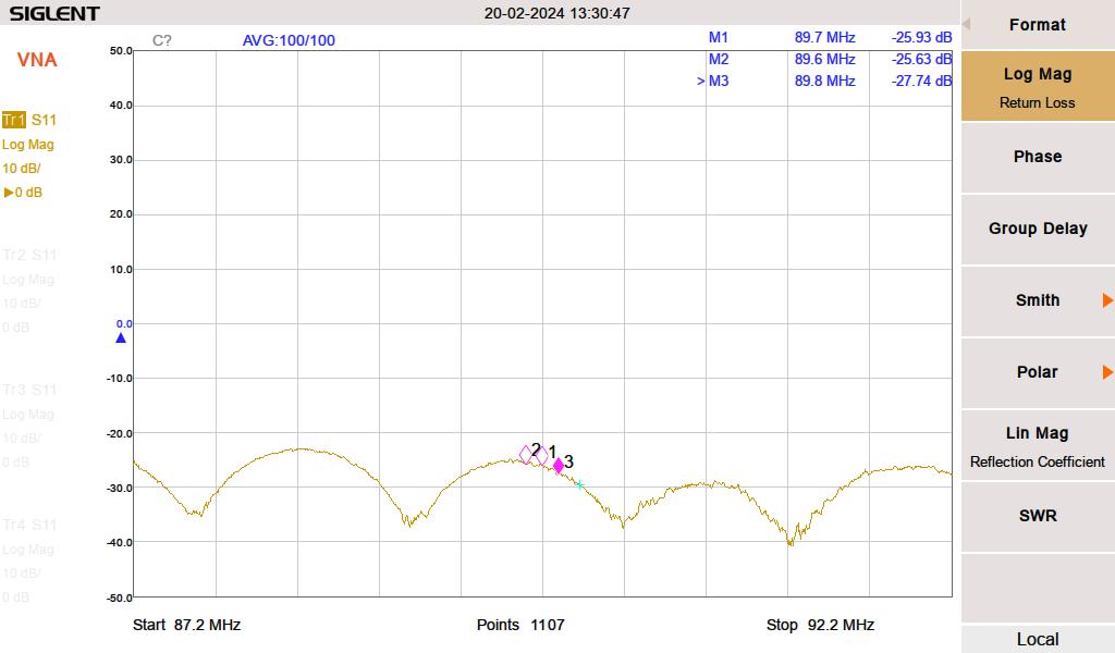
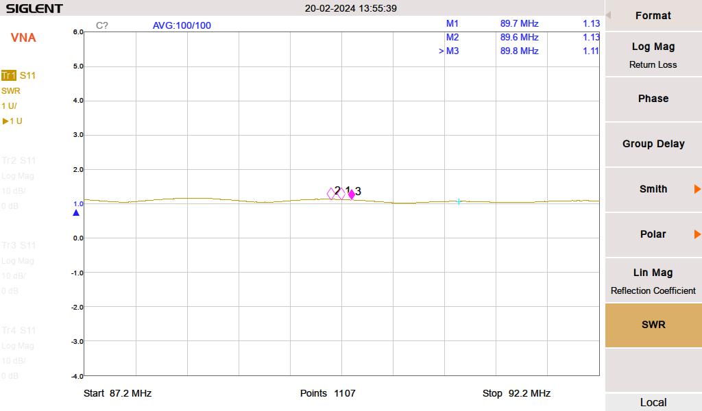
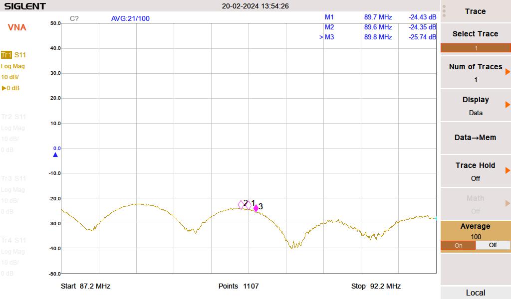
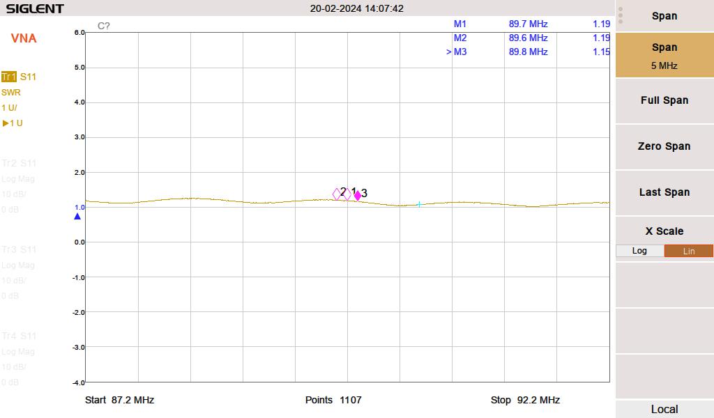
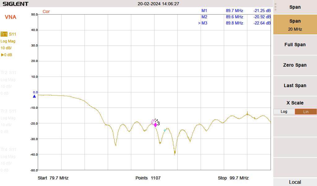
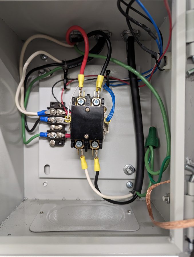
The input filters needed a slight adjustment to compensate for the difference between the test load they were tuned to and the actual antenna load they will be running into

Touching up input filters

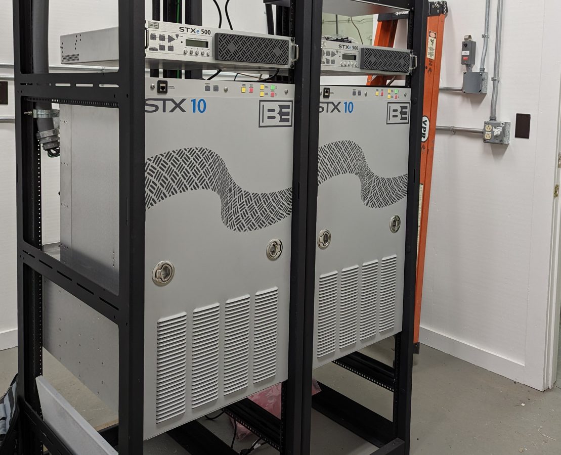
Two of the transmitters are Broadcast Electronics STX-10 units. We have had good service from the STX-10 which was installed on Mount Beacon a few years ago.

Pair of BE STX-10 transmitters

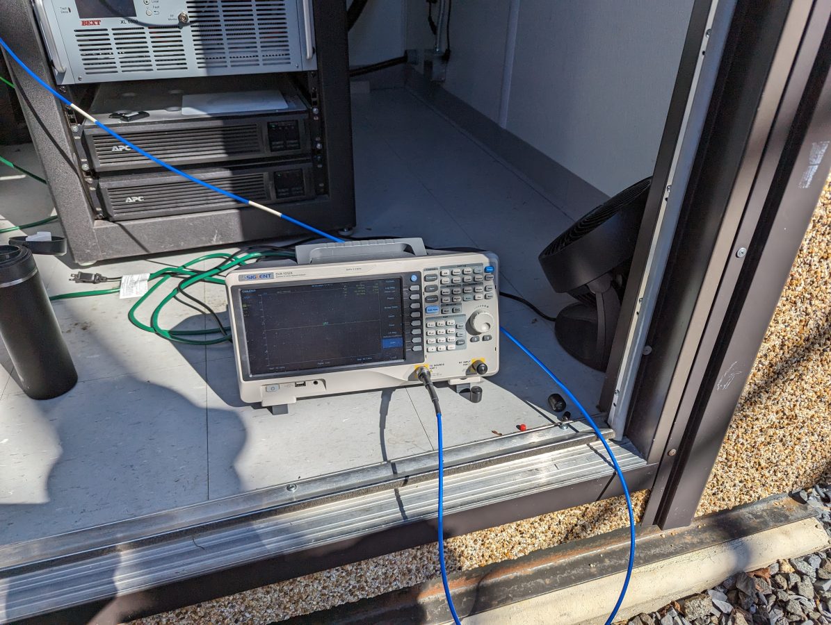
We are waiting for the Comrex Bric Link III to come back from the factory after their firmware update. They are to be used for the STL. Once they are returned, we should be good to go for site turn-up.

The Shively 6025 Broadband Log Periodic Antenna

Several companies make variations of this antenna; Scale FM-CL is a lower-power version that is used mostly by translators. They are highly directional and can be installed in a vertical, horizontal, or cross-polarized (45-degree slant) manner. This model input power is 5 KW per bay and the manufacturer’s specification is for 1.28:1 or less VSWR across the entire FM band. In the slant configuration, which Shively states is right-hand circularly polarized, the gain is 4.03 dB.

I recently did some work onsite for WXMD, California, Maryland. They were having some issues with high reflected power readings on their transmitter and suspected an antenna or transmission line problem. The station has been on the air for about 10 years and began having issues late last year after a thunderstorm passed through the area.

WXMD California, MD South East Bay Shively 6025 antenna

The main issue was that the transmitter was showing 243 watts of reflected power with 9800 watts of forward power, while the inline watt meter showed 37 watts. As part of the repairs, a new 1 5/8 transmission line was run up the tower replacing the old line which was damaged at the power divider input connector. A new power divider was also installed. Was the antenna still defective? Was the new transmission line and/or power divider defective? Was there an issue with the inline watt meter? Questions, questions, questions…

Thus, several sweeps were needed to verify things:

1 5/8 inch line terminated at the power divider with known good load

This antenna has a power divider that splits the power between a southeast-facing antenna bay and a southwest-facing antenna bay. To be sure that we were not dealing with a bad connector or transmission line, the line was swept in isolation from the input of the inline watt meter to the input of the power divider. This showed that the transmission line, connectors, elbows, and inline watt meter were all good.

Southeast Antenna SWR
Southeast antenna return loss

Next, each antenna bay was swept individually. The power divider port going to the disconnected antenna was terminated with a known good 50-ohm load.

Southwest antenna SWR
Southwest antenna return loss

Once the individual bays, jumpers, and power divider tested good, the entire antenna system was swept.

Full antenna SWR

With everything connected, the SWR showed 1.19:1. Not ideal but not terrible either. The inline watt meter readings were verified with a precision watt meter and the final SWR calculated by hand was 1.16:1.

Full antenna return loss

Therefore, the antenna system is performing within the manufacturer’s specifications.

Network analyzer

The American Amplifier Technology inline FM watt meter was then checked with a precision power meter. The readings on that device were more or less in line with the precision power meter, thus the transmitter directional coupler is out of calibration.

Mini-Circuits Precision Power meter, Forward Power
Mini-Circuits Precision Power meter, Reflected Power

The transmitter shelter is just large enough for one rack. Thankfully, the weather was cooperative, we were able to work outside. Overall, it was a productive trip and an enjoyable experience.

De-icer controller

Call it climate change or an unfortunate coincidence; we seem to be getting more icy weather in this area. It used to be this region would see one mild event every one or two years. Recently, however, we are getting two to three moderate to severe events per year.

This can create problems for the utility company. Even if the power stays on, the transmitter may not. Excessive ice on the antenna may cause the transmitter to fold back or shut down completely.

We have several clients that have various FM antennas with electric resistance type de-icers. One client has three such stations however I found there were no automatic controllers at any of them. Back in the day, when there were people working at the station, they probably turned the de-icers on and off manually via the remote control. These days, not so much. When we began servicing these facilities, the previous engineer stated that he turned the de-icer breaker on around Thanksgiving and turned it off around Easter. Not terribly efficient.

As a part of moving into a new transmitter building, I began looking for something that would automatically turn the de-icer on when it is precipitating at or close to freezing temperatures and then turn it off after a couple of hours. That would certainly reduce the electric usage for that transmitter site and keep the transmitter happy.

I found this simple snow melt controller:

ETI LCD-8 snow melt controller

This is sold on Amazon for about $570.00. This has an internal relay that can switch 240 volts at 16 amps. However, that 240-volt heating circuit goes up to the top of the tower where the FM antenna is mounted making it vulnerable to lightning damage. I figured an outboard relay switched on and off by this controller was a better way to go. That way, there is an operating indicating lamp and a bypass switch.

De-icer controller relay

Outdoor icing sensor mounted on the ice bridge.

Now, the de-icer stays off most of the time. When it is needed, it comes on automatically and turns off three hours after the precipitation has stopped. Since installing last fall, it has worked well and the station stayed at full power through at least two ice events.

I measured the current on each leg, which was 2.6 amps or 624 watts. That is the same as it was before. A quick calculation, I estimate the number of hours this system was previously energized when the breaker was left on all winter to be roughly 3,400. Thus 3,400 hours x 624 watts = 2112 kWh. These days, our electric rates are running $0.16 to $0.18 per kWh so the total cost would be $380.00 to run continuously. The control system will pay for itself in less than two years.

North Adams Tower update II

Work continues on rebuilding the North Adams tower after the collapse of March 2014.  Over last winter, a new tower was erected.  This is a fairly substantial tower.

New North Adams tower on ground
New North Adams tower on the ground
North Adams new tower erected

In the interim, a new Shively 6810 four bay half wave spaced antenna was ordered. This antenna will be combined for two stations, WUPE-FM and WNNI using a Shively 2630-2-06 branched combiner. The 70 foot utility pole next to the building will be retained as a backup facility for both stations. The Shively Antenna went up in stages.

New WUPE-FM and WNNI Shively 6810 antenna
Tower climbers rigging tower for new antenna

Prescott Tower from Rutland Vermont was on site to do the tower work. They were the primary contractor for installing the new tower and did a really nice job of it.

New North Adams tower ice bridges to various shelters
Hanging the top two bays of new antenna
Hanging the top two bays of the new antenna
Lift of bottom two bays and first tuning section
Securing bottom section and bolting bays together
Securing the bottom section and bolting bays together

After that, there were twenty feet of rigid line, another tuning section, then the 1 5/8 inch heliax into the transmitter room. The antenna was tuned and the load looks very good. We are waiting for the electrician to finish wiring up the new racks and we will move both stations into their new home.