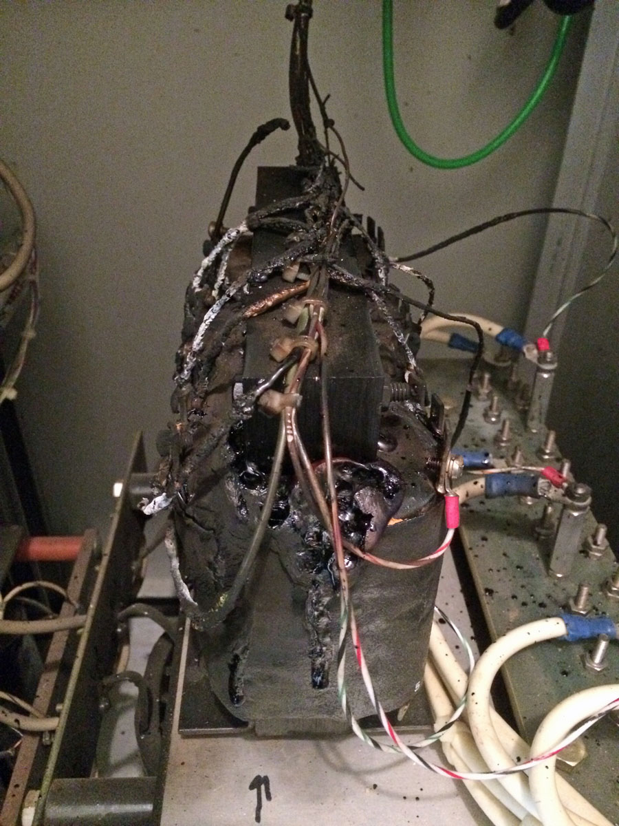
After one of our clients had an FM station go off the air over the weekend, I investigated and found this:
Transformer meltdown
Looks like something one might find in the reactor room at Chernobyl or Fukushima.
Transformer melted down
This is at one of those sites with three phase open delta power. Needless to say, the transformer is toast, perhaps the entire transmitter too. This will be another fun transmitter-scrapping project. I was thinking about this; over the last five years, I have scrapped at least ten to fifteen old tube transmitters. The old tube types are going away fast, as are those that can still work on them.
I alluded to this in an earlier post: Open Delta three phase service. Some transmitter sites are fairly remote and three-phase power is not available. Occasionally, with lower-powered radio stations, this is acceptable because those transmitters can be configured to run on single-phase power. However, almost any transmitter above five kilowatts or so will require three-phase power. This is the case at the WQBJ transmitter site in Palatine Bridge, NY. The site is located in the middle of farmland and only has single-phase service. The nearest three-phase service is several miles away and the utility company wants several hundred thousand dollars to upgrade the line.
WQBJ transmitter site electrical service
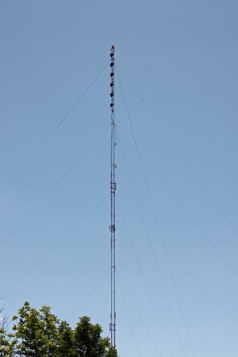
The station is a class B FM with a six-bay full wave-spaced antenna. Even so, the TPO is 17 KW, which makes some type of three-phase service a requirement.
WQBJ six-bay Shively 6810 antenna
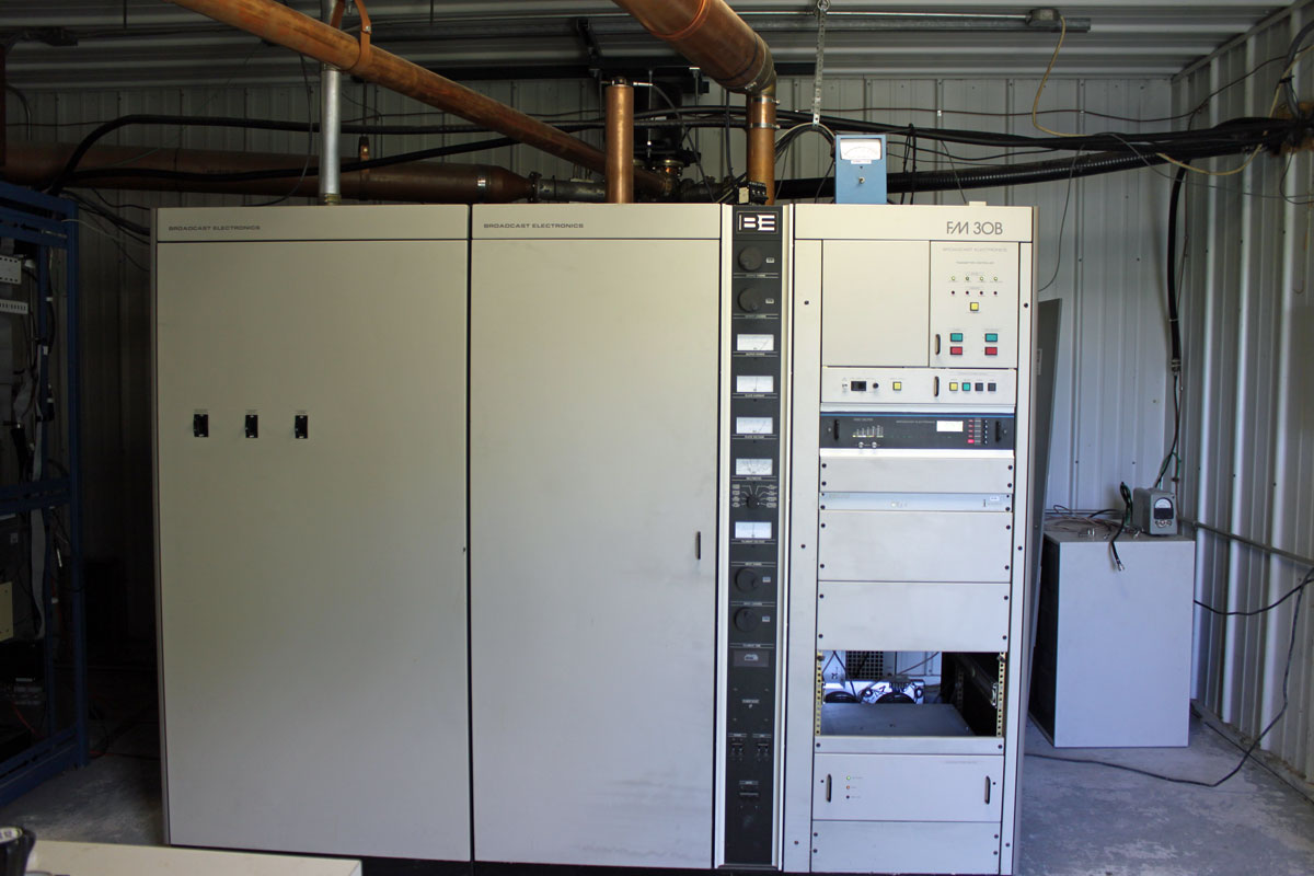
The main transmitter is a Broadcast Electronics FM30B, which is now 25 years old.
WQBJ main transmitter, Broadcast Electronics FM30B
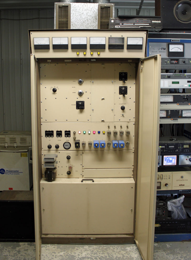
The backup transmitter is a CSI FM20T, which is almost forty years old.
WQBJ backup transmitter, CSI FM20T
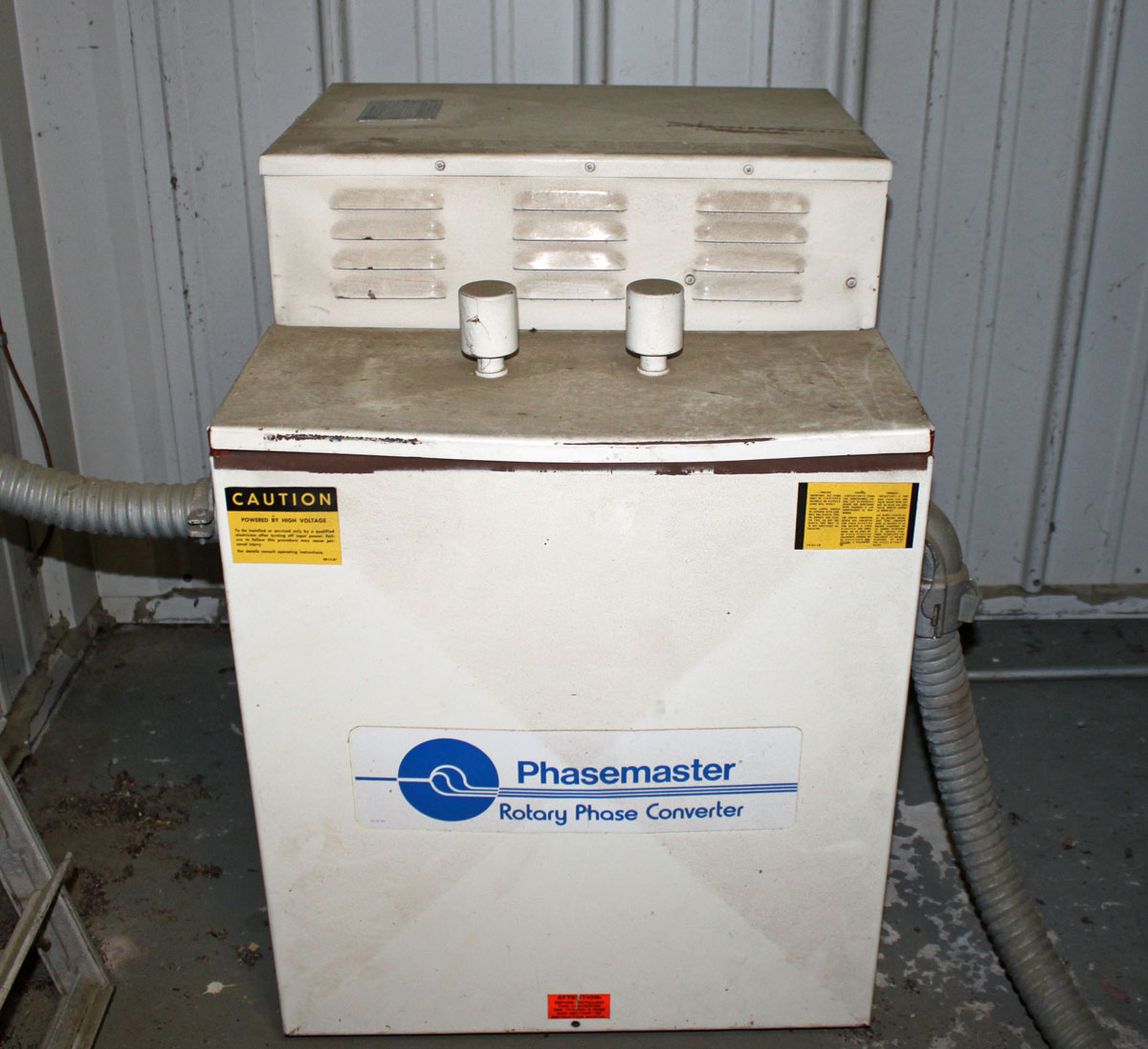
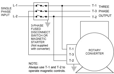
Rather than do an open delta service, which is not desirable for several reasons, both transmitters have their own rotary phase makers. From a reliability and redundancy standpoint, this is the right way to equip this site. The rotary phase makers are essentially a motor generator combination which takes the split phase power and generates a third phase.
WQBJ Phasemaster type T, backup three-phase converterPhasemaster parallel connection diagram
The phasemaster is is a 40 KVA unit and is connected to the backup CSI transmitter
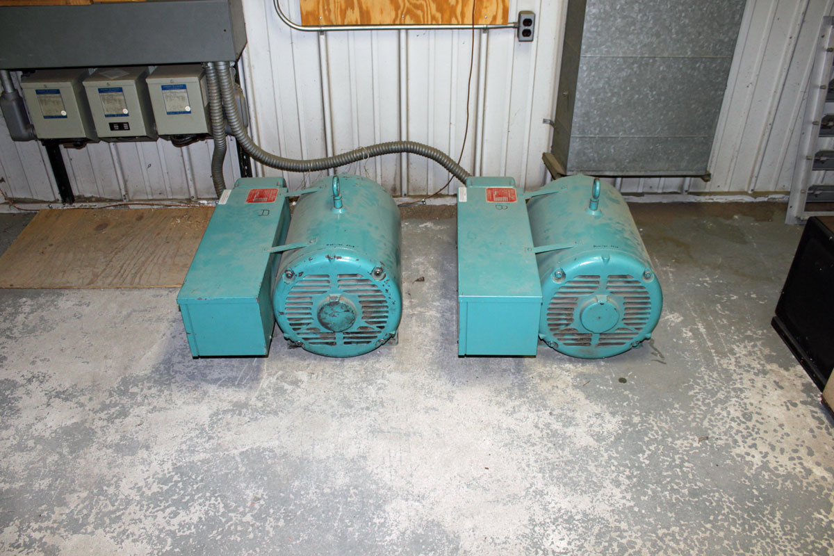
WQBJ ARCO Roto Phase, main three-phase rotary converter
The Roto Phase unit for the main transmitter is actually two 40 KVA units connected in parallel through dry core isolation transformers. Incidentally, the Roto Phase units need to have their bearings changed every ten years or so. This requires the units be disconnected, placed up on their end. To get the old bearing out, the housing has to be cooled with liquid CO2. Both units are due for new bearings soon, which should be a pleasant job indeed.
Several months ago, I drove up to an FM transmitter site, looked up at the utility pole, and saw this:
Three Phase open delta transformer bank
Three-phase open delta is a bad hombre. Most, if not all, transmitter manufacturers will void the warranty of any transmitter connected to a service like this. What is perplexing is it appears that all three phases are available on the primary side, why would this be necessary? Perhaps it was not always so at this location. Regardless, this was the source of power for 20 KW FM transmitters since 1958 until we moved it to a new building last month.
According to a GE publication on transformers, open delta 3 phase power is undesirable because:
Although this connection delivers three-phase currents which are approximately symmetrical to a three-phase symetrical load, the currents flowing in the high voltage circuit are not equal nor are they 120 degrees apart. The maximum safe output of the bank operating in this manner is 58% of a 3 pot Wye/Delta bank. The system is grossly unbalanced, both electrostatically and electromagnetically.
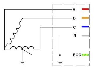
Schematically, it looks like this:
3 Phase open delta power
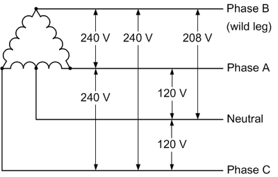
Regular 3 phase delta looks like this:
3 phase delta power
Most utility companies will not hook up 3 phase delta on the customer side anymore because the “high” or “wild” leg, which as shown in the diagram runs a good deal higher than 120 volts to neutral. Hook up a high leg to a single phase 120 volt piece of equipment and wait for the power supply to blow up. Also true with 277-volt lighting circuits, as my assistant once found out with the Coke Machine in the break room. The new 3 phase service will almost invariably be 208 wye unless there is some very compelling reason, which is fine.
There are many ways to get around three phase open delta, perhaps the best is a rotary phase converter. This piece of equipment will take a 240-volt split phase and add a third leg. These legs will not be 120 degrees apart, as they would be in a true three-phase, however, they will be close enough that 3 phase motors and transformers will be happy.
Rotary Phase converter
This leads to an unbalanced voltage/current condition which needs to be accounted for in the design of the unit. The second way to do this is to power a three-phase generator with a split-phase motor. This will completely isolate the 3 phase equipment from the utility service and provide for true three phase power.
The downside to any motor/generator or rotary converter is moving parts and conversion inefficiencies. At any transmitter site that uses this type of equipment, either a backup power converter or a lower power split phase backup transmitter should be installed. With all mechanical things, eventually, this will need to be repaired and it would suck to be off the air while that is happening.
Regardless of any of that, this particular service is about to be disconnected permanently. Good riddance.
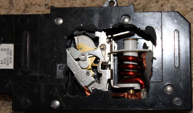
Just because I can, here are a few pictures of the inside of a rather expensive 80-amp DC-rated circuit breaker:
80 amp DC rated circuit breaker open
What is the difference between a DC-rated breaker and an AC-rated breaker? Good question. Because DC is, well DC, the current is continuous. Once an arc is struck, greater separation is needed between conductors to extinguish the arc. Using an AC breaker in a DC application can lead to an internal arc and fire. That would be a bad outcome.
Just how did the insides get exposed, one might ask? Well, there I was working on a solar installation with said breaker placed on a horizontal surface waiting for installation when somehow it was knocked to the floor, creating a large crack in the side of it. Angry I was because this thing set me back some fifty dollars.
80 amp DC rated circuit breaker closed
This picture shows the breaker closed, the contacts are still undercover to the left of the exposed parts. What is cool is one can get a good idea of how a circuit breaker works. As the current flow increases, the magnetic field around the coil increases. When it reaches the trip point the small steel piece is pulled down, causing the mechanical assembly to unlock and open the contacts.
Old tech stuff that is taken for granted probably has saved millions of lives since electrical use became widespread.