It is a pretty good simulation of what will happen on November 9th. The script used is not the actual script that will be used for the national test.
After the test, the video shows how to bail out of the national test in the event that a valid EAN is not received. This is important information, as this particular failure has occurred many times in the past. If the LP-1 or PEP station that transmitted the test fails to send a valid EOM, the EAS unit will continue to transmit that station’s programming indefinitely. If the LP-1 or PEP station resumes regular programming while the EAS unit is relaying their programming over the air, that would be a good indication that the LP-1 or PEP station has failed to send a valid EOM.
This is a test, you have been warned. The FCC has scheduled the first nationwide mandatory EAS test for November 9th, 2011 at 2pm EST (1900 UTC). According to James A. Barnett, Jr., Chief, Public Safety and Homeland Security Bureau:
For the test, FEMA will trigger the EAS “cascade” architecture by transmitting the EAS code used for national level emergencies to the first level of broadcast stations in the national-level of the EAS, which in turn will rebroadcast the alert to the general public, as well as to the next level of EAS participants monitoring them. This should continue through all levels of the system until the alert has been distributed throughout the entire county.
Since this date is beyond the CAP deadline of September 30, 2011, it seems like CAP would be the distribution method, but there is not nothing I can find to verify that. The above paragraph makes it sound like the PEP system might be used.
This will be an interesting evolution for a number of reasons. If the EAS system fails to operate as planned after giving five months warning for a nationwide test, it would point toward a fundamental design flaw in the system. A more realistic test of the EAS system would involve perhaps one hour’s notice and then trigger the event. Notice should be given so that broadcast station personnel can answer questions from the listening and viewing public.
Then there is the EAS EAN protocol itself. There are many that feel, rightly or wrongly, that the federal government should not be able to take control of privately owned broadcast stations and cable systems for any reason. The way that the EAS encoder/decoder units are now required to be wired into the audio air chain means it would be very hard to override any mandatory alert, such as an EAN if there were a reason to do that. There have been several instances of false alerts, WGN-AM being the most recent, where programming on downstream broadcast and cable systems was disrupted for several minutes.
So, save the date. It will no doubt be interesting to see how this all works.
Lots of ink has been spilled about the new CAP (Common Alert Protocol)implementation and what it all means. Since the FCC started the six-month CAP clock ticking on September 30th of last year, they have extended the deadline by six months to September 30, 2011.
The idea of upgrading EAS is a good one. When EAS replaced EBS in 1997 it was supposed to do away with the over-the-air relay system also known as the daisy chain. This was left over from the 1960s CONELRAD system implemented by Kennedy. That replacement never occurred and stations today are still monitoring other broadcasting stations for their EAS alerts. The daisy chain was and still is the source of all EBS and EAS failures.
CAP is supposed to eliminate that weak link by allowing the EAS unit to access government IPAWS message servers directly, allowing FEMA to automatically send out alert messages to designated areas. This has some libertarians in an uproar, as they see government intrusion and taking over privately owned radio stations to broadcast emergency information as a form of tyranny. In as much as the definition of “emergency message” has not been codified by FEMA in any of their information, they may have a point. In the past, the general definition of emergency communications was those that were pertaining to imminent threats to the safety of life and property. According to Executive Order 13407, Public Alert and Warning System, the purpose is to:
…have an effective, reliable, integrated, flexible, and comprehensive system to alert and warn the American people in situations of war, terrorist attack, natural disaster, or other hazards to public safety and well-being…
Which is certainly much broader in scope. How does one define a hazard to “well-being?”
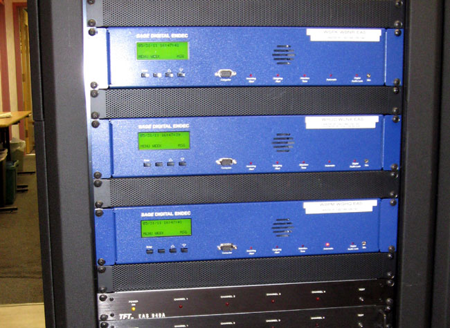
SAGE alerting systems have completely revamped their ENDEC to include CAP 1.2. It uses the internet to connect to IPAWS servers and receive CAP messages. As the SAGE ENDEC owners manual notes, participation in local and state-level alerts is at the discretion of the station management, as regulated by the current version of FCC Part 11. National-level participation is mandatory:
Participation at the national level is mandatory for most broadcasters. You may petition the FCC to become a “Non Participating National” station, but you must still receive and broadcast the EAN code, and then leave the air. These requirements are always evolving, refer to the FCC rules, in particular CFR 47 Part 11 for details.
Oftentimes, it is the local emergencies that are the greatest and most immediate threats to human life; the tornado, the tsunami, etc. Those are the most pressing threats, not the national-level alerts, which were implemented in the 1960s to warn of a major attack from a foreign country, something not very likely these days.
SAGE ENDEC
Further, the internet has proved to be less than reliable when trouble occurs. During the terrorist attacks on 9/11/2001, dial tone, cellphone, and internet service for much of lower Manhattan were disrupted because the TELCO facilities were in the buildings that were destroyed. Most internet services rely on wired or fiber optic services provided by TELCO or cable companies, which can be affected by power outages, damaged infrastructure, and so on, which would likely occur in a major emergency.
It does not seem to be the most robust method for the distribution of emergency messages.
At the place of my former employment, there is an issue with AM reception. The building is full of old, electrically noisy fluorescent light ballasts, computers, mercury vapor parking lot lights, and every other electrical noise generator under the sun. The second issue is that one of the EAS monitor assignments for two FM class B stations is WABC in NYC. Under normal conditions, WABC puts a fine signal into the area. Listening to it is not a problem at my house, in the car, and whatnot. However, at the studio, the station is audible but terribly noisy. Every time one of those FM stations ran a required monthly EAS test originating from WABC, it was full of static and just sounded bad on the air.
The state EAS folks were inflexible as to the monitoring assignment. “WABC is the PEP station for NY. You should have plenty of signal from WABC at your location,” said they.
At one time, the studio had an active loop antenna (LP-1A) from Belar, which worked but also seemed to amplify the noise. I decided that the best thing to do was go big and ditch the preamp. I made a diamond-shaped receiving loop on two pieces of two-by-four by eight-foot lumber. I wound four turns of #14 stranded wire around this frame and made a 4:1 balun to feed the unbalanced 75-ohm RG-6 coax.
That cured the noise problems and for eight years, WABC sounded pretty good on the EAS monitor.
Fast forward to about a week ago. The roof at the studio building was being redone and all the monitor antennas had to be removed from the roof. The homemade loop was not in good shape. The balun box was full of water, the lumber was cracking and falling apart, the insulation was degraded by UV exposure, etc. My boss asked, “How much to make a new one?” So I said something like forty dollars and a couple of hours. He then said, “Make it so we don’t have to ever make another one.”
Music to my ears. I started by checking my assumptions. I made a model and ran NEC to see what the electrical characteristics for that size loop were on 770 KHz. It came out better than I thought, with about 1-ohm resistance and 282 ohms inductive reactance. Fooling around a little more showed that roughly 1.3 uH inductance and 720 pF capacitance in an L network would bring this in line for a 50-ohm feed point. Since this is a receive-only antenna, that is not a prime consideration. I am more concerned with noise reduction and maintaining at least the bi-directional quality of a loop antenna.
NEC 2 model AM receive loop
Then, I decided to get fancy. What if the capacitance was put on the end of the loop to ground instead of the feed point? That, in effect, should make the loop directional off of the unterminated side. Driving the feed point with a 9:1 balun would also bring up the inductance on the feed point. Finally, grounding the whole thing with a separate ground lead might also get rid of some noise.
The final configuration looks something like this, which is essentially a top-loaded vertical:
Low noise AM loop antenna
Now to build it.
Once again, I felt that a non-conductive support was needed, so I used two by four by eight-foot lumber, but this time I painted them with oil-based paint. The side length worked out to be 5.7 feet per side, or 23 feet per turn for a total of 92 feet of wire.
I purchased 100 feet of PV (photovoltaic) wire (Alpha wire PV-1400), which is UV, heat, and moisture resistant and designed to last for 30 years in outdoor, exposed environments.
For the balun box, I used a metal outdoor electrical box with a metal cover. I put a ground wire jumper between the box cover and the ground common to maintain shielding. I used a water-tight bushing to feed the antenna wires and the ground wire into the box. I drilled a 3/8 hole for a type F chassis connector. Everything was given a little extra waterproofing with some silicone-based (RTV) sealant on all threaded junctions.
The spreaders for the wire windings are UV-resistant 1-inch PVC conduit. I drilled four holes, three inches apart in each spreader to run the loop wires through.
The balun is 7 trifiler turn of 24 AWG copper wire on an FT-43-102 toroid core. Trifiler means three wires twisted together before winding the toroid core.
I used all stainless steel screws and mounting hardware.
The loop is terminated with a 500 pF, 500-volt ceramic capacitor to ground. Once in place, I am going to experiment with this by jumping it out of the circuit to see what effect it has on noise and signal strength. I may also try replacing it with a 200-ohm resistor and or a 1000 pF capacitor.
The assembly was pretty easy, although time-consuming. My four-year-old son helped me paint the wood and string the wires through the spreaders.
I soldered all wire connections with 5% silver-bearing solder.
When the whole thing was assembled, I tested it out with my Drake R8 receiver. It performs much as expected, with low noise, directional away from the terminated wire loop. It does not appear to be too narrow-banded either, as the stations on the high end of the dial were also received with good signal strength.
Next was loading it on the pickup truck, driving it in, and mounting it on the studio building. I got some funny looks from my fellow travelers, then again, I usually do.
For the ground, I purchased an eight-foot copper-clad grounding rod and pounded it into the ground at the corner of the building. This area is always wet as it is the lowest area around the building and all the gutters drain there. This is not best RF ground, but for the purposes of this antenna, it should work fine. I used about 28 feet of leftover #12 stranded wire from the ground rod up to the balun box and connected it to the common ground point inside the box.
The frame itself is mounted on a standard wall-mount antenna pole. Stainless steel clamps hold the wood frame to the pole.
Once it was installed, I used my Kenwood R-2000 receiver to find the best mounting azimuth and locked everything down. I also put a toroid on the RG-6 coax coming up from the rack room to keep any shield noise from getting into the antenna.
AM receive loop PVC wire spacers
AM receive loop wood frame
AM receive loop balun transformer
The tuning capacitor is in there too, behind one of the loop wires.
AM loop antenna installed on roof
Antenna installed. I did try substituting the 500 pF capacitor with a 220 resistor. The signal strength came up somewhat, but the noise increased more, therefore the capacitor is a good termination for this antenna.
With this antenna, the signal from WABC is nice and clean and sounds good on the FM station when a monthly EAS test is retransmitted.