1001 uses for a NanoVNA

Recently, I pried open my wallet and plunked down the sum of $150.00 for one of these little devices. Now, to be certain, this is not a replacement for a real VNA, especially at a high-power broadcast site. However, it can be used for basic troubleshooting and I have had a good deal of fun fooling around with it.

First, a few quick specifications:

  • Type: SSA-2N NanoVNA V2.2
  • Frequency range: 50 KHz to 3 GHz
  • Power output: -50 to +10 dB
  • Measurement points: 201 (or 1024 with software and computer)
  • Measurement types: S11, S12 and S21
  • Screen Size: 4-inch touch screen
  • Traces: up to 4
  • Battery: 3000mAh Lithium Ion
  • Software OS (VNA-QT): Win 7, Win 10, Linux, MacOS

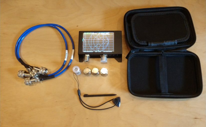
The unit I purchased came with a small carrying case, calibration loads, and test jumpers. The software is downloadable and easily configured.

What I really like about it is the internal battery and the touch screen.

So what can it be used for?

  • Test a coaxial cable
  • Measure the length of a coaxial cable
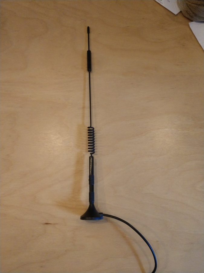
  • Figure out what frequency an antenna is designed for
  • Tune a 1/4 wave stub to make a notch filter
  • Measure the characteristics of a crystal/holder
  • Measure a capacitor
  • Measure an inductor
  • Tune a parallel resonant LC circuit to make a notch filter
  • Tune a filter can
  • Test a high pass, low pass or band pass filter
  • Sweep an antenna (Simple AM, FM, RPU, STL, WiFi)
  • Check isocouplers for proper circuit functioning
  • Etc

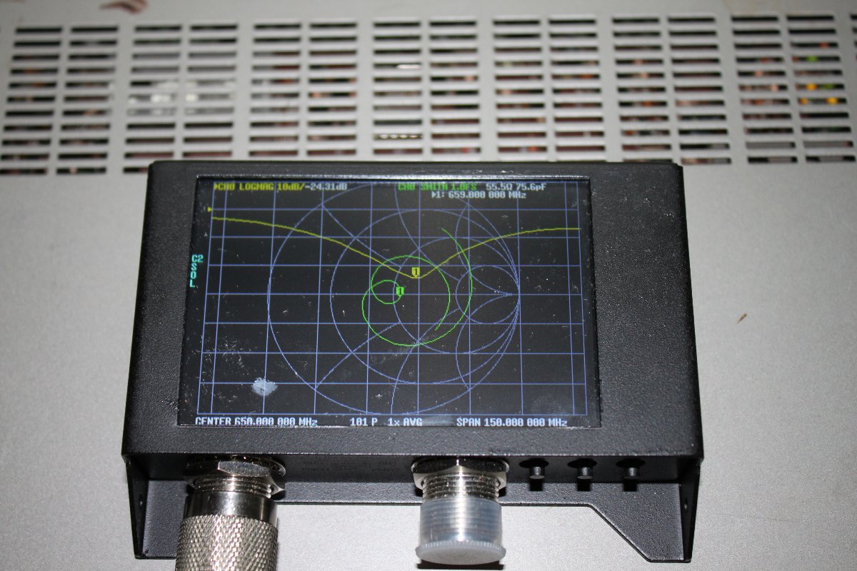
Pretty much anything you need to know about RF antennas, filters, and transmission lines can be learned with a VNA. One thing to keep in mind; the measurement points are limited, especially in the stand-alone mode. Thus, the smaller the frequency span, the better the measurement resolution will be.

What is this antenna for?
Antenna under test, 659 MHz center frequency

While this is a very inexpensive device designed mainly for Amateur Radio, it can be useful to diagnose antenna and transmission line problems. Would I depend on it to make precise measurements? No. Especially things required by the FCC like base impedance measurements on an AM tower or channel filter measurements for a TV station. Would it work at a high RF transmitter site with multiple AM/FM/TV transmitters? No and chances are you might burn out the front end. Those types of things are best done with professional equipment that has much better accuracy and resolution.

It is a pretty good little tool for basic troubleshooting. One can look at the individual components of an AM ATU for example, or measure the input impedance to see if there has been a shift (should normally be 50 ohms). It is small enough that it can be included in a basic tool kit. It is self-powered. Not bad at all for the price.

The unitless coefficient of Zorch

Zorch is a term used to describe an over voltage or over current condition that usually leads to catastrophic failure, e.g. the power supply was zorched by lightning. There is also a quality to radio signals that defy and exceed theoretical definitions for service contours or power density.  That is quality defined as:

Zorch (adj): The ability of an RF signal to be received in unlikely locations; outside of predicted service contour, in steel structures, underground facilities, tunnels, etc.

It brings to mind the saying, “antennas are not amplifiers and amplifiers are not antennas.”

ERI circularly polarized 2 bay antenna

During the earlier stages of FM broadcasting, there was a notion that costs could be reduced by increasing antenna gain and reducing transmitter size. While theoretically, ERP (Effective Radiated Power) is ERP, broadcasters soon learned that high gain antenna, low TPO (Transmitter Power Output) installations lacked building penetration and had other reception issues.  Realizing that there is a trade off between antenna bays, transmitter power output especially in difficult reception areas, a great debate occurred and continues on what the optimal system is.  The answer is, it depends on the receiving environment.

Where this technical detail can be really important is with lower powered FM stations; Class A and LPFMs to be exact.  They are already battling against bigger stations that have tens or even hundreds of times  more power.  Certainly an LP-100 station has it’s work cut out for it.  The choice of antenna is perhaps one of the most important technical decisions to be made.  Choosing the right balance of antenna type, antenna gain, antenna height and transmitter power output can greatly influence reception reliability and thus coverage area.

A good study of this quality can be had by looking at various LPFM installations:

Station ERP (watts) Antenna Type Antenna Gain (power) TPO (watts)* Coefficient of Zorch
100 1 bay vertical 0.92 127 0.1
100 1 bay circular 0.46 253 0.4
100 2 bay vertical full 1.98 58 0.15
100 2 bay vertical half 1.40 83 0.2
100 2 bay circular full 0.99 118 0.5
100 2 bay circular half 0.70 166 0.7
100 3 bay circular full 1.52 77 0.46
100 3 bay circular half 1.01 115 0.52

*Includes 100 feet of 1/2 inch foam transmission line, Andrew LDF4-50A, loss of 0.661 dB  at 100 MHz, or 0.859 power gain.

Stations should try to get the transmitting antenna as high up as permitted without reducing ERP.  In other words, the FCC allows 100 watts ERP with 98 feet Height Above Average Terrain (HAAT) radiation center in their current LPFM rules.  Being lower in height will reduce the coverage area.  Going over 98 feet HAAT will cause the station’s power to be reduced, which will lower the coefficient of zorch accordingly.  Therefore, getting as close to 98 feet HAAT, which is different than 98 feet above ground level in many places, will net the best performance.

If a singular polarization (horizontal or vertical) is desired, vertical polarization should be chosen, as most mobile reception is by a vertical whip antenna.  For best reception performance, a circularly polarized antenna will work best, as receiver antenna orientation will not effect the signal reception.  A circularly polarized antenna has better building penetration and multi-path characteristics.  The FM broadcast circularly polarized antenna in not a true circularly polarized antenna, it is actually unpolarized.

The use of a multi-bay antenna has the effect of focusing the RF radiation outward, perpendicular to the element stack, thus limiting the radiation directly up or down from the antenna.  This is more pronounced with one half wave spaced antennas, which may be an environmental consideration in heavily populated areas.

Thus, the best coefficient of zorch for an LPFM station would be a circularly polarized, 1/2 wave spaced, 2 bay antenna.  This antenna would have some gain over a single bay antenna, take up less room on a tower than a full wave spaced antenna, offer good RF protection performance for the general public living and working under the antenna, reduce wasted upward radiation and offer good building penetration for the ERP.  It would require a slightly larger transmitter and more electricity, but that trade off is well worth the effort.

Now where is that BNC male to N female adaptor

Working with RF can produce some head scratchers.  Most transmitter manufactures tend to use the same type of connector for things like exciter RF outputs and composite inputs.  Over the years, I have become well stocked with all sorts of BNC and Type N connectors.  Satellite equipment uses Type F connectors, Analyzers use Type N, Oscilloscope uses BNC,  GPS equipment uses SMA and so on.  Except when they don’t.  As any good engineer will tell you, when they don’t will be in the middle of the night at some mountain top location while the station is off the air.

After one such incident, I invested in a TPI-3000A adaptor kit.  This kit has both the male and female versions of Type N, F, SMA, BNC, TNC, UHF, UHF mini and RCA.  They can be mated in any combination using the Universal interface.

TPI 3000A adaptor kit

On more than one occasion, this little kit has meant the difference of between being back on the air or driving down the mountain to look for an in between series adaptor.  A couple of recommended additions include a 7/8″ and 1 5/8″ EIA flange to type N male.

TPI-3000A inside
TPI-3000A inside

They can be a little pricey, however, I have seen several for sale on eBay for less than $100.00.  The key to not loosing the various little parts to this kit is to write a little note detailing the date and location where the adaptor was used,  then stuff it in the empty hole.  Hopefully, when permanent repairs are made, the adaptor will be retrieved.