All digital Medium Wave transmission

With the approval from the FCC for all digital broadcasting on the Standard Broadcast (AKA AM, Medium Wave, Medium Frequency) band, it might be interesting to dissect Xperi’s HD Radio MA3 (HDMA3) standard a little bit. It might also be interesting to compare that to DRM30 which has been in use in many other places around the world for several years now.

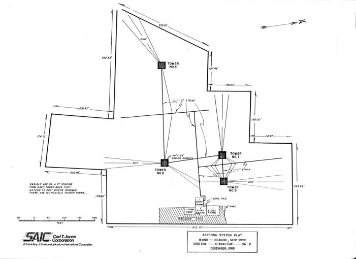
First, I will dispense with the givens; HD Radio sounds better than its analog counterpart. I have also listened to DRM via HF, and that too sounds better than its analog counterpart. Of interest here is whether or not either digital modulation scheme improve reception reliability and coverage area. Medium Wave has a distinct difference from other frequency bands as it can cover vast areas. Something that has been dismissed in recent years as unneeded due to reduced maintenance schedules and the cost of keeping directional antenna systems in tolerance (thus increasing skywave interference).

Secondly; after reading several studies of HDMA3 and DRM30, I will concede that both systems perform betterAnnex E, Ref 2; Section III para C, Ref 6 than their analog counterparts in a mixed digital analog RF environment. Both systems have features which can be used to improve reception during night time operation. Skywave exists, whether or not people want it. If it is not desired as a reception mode, it still has to be dealt with from an interference perspective.

The two main complaints against Medium Wave broadcasting is perceived reduced audio quality (over FM) and interference. The interference comes in two flavors; electrical impulse noise and broadcast (co-channel and adjacent channel AM stations). Both are problematic. To some extent; both can be somewhat mitigated by an all digital transmission. However, if the interference noise becomes too high, the program will simply stop as the data loss becomes too great to reconstruct the audio program.

Of further interest here is the technical aspects of both systems and whether or not one would be superior to the other for Medium Wave broadcasting. I found this comment on a previous post to be particularly interesting:

DRM and HD both use OFDM, but the parameters are quite different, eg. the length of cyclic prefix which determines the performance in sky/ground wave interference are different by a factor of 9 (0.3ms vs 2.66ms). That is why DRM is much robust than HD.

https://www.engineeringradio.us/blog/2020/04/all-digital-am/

First of all, is this a true statement? Secondly, does the cyclic prefix make a difference in sky wave to ground wave interference? Which system might work better in a broadcast service where there are 4560 stations transmitting (as of 9/2020) and creating interference to each other? Finally, could the implementation of either system make a worth while difference in the quality and reliability of Medium Wave broadcasting in the US?

To answer these questions, I decided to begin with the technical descriptions found in the definitive documents; NRSC-5 D 1021s Rev GRef 1 for HDMA3 and ETSI ES 201 980 V4.1.1Ref 2 for DRM30.

There are many similarities between the two systems; both use COFDM modulation schemes, both have various bandwidth and data rates available, both use audio codecs that similar, both have some type of FEC (Forward Error Correction) system. I prepared a chart of these characteristics:

Feature/SpecHDMA3DRM30
Carrier typeFull CarrierNo Carrier
OFDM subcarrier spacing181.7 Hz41.66, 46.88, 68.18,
and 107.14 Hz
Effective Data Rate, 20 KHz Channel40.4 Kbps30.6 – 72 Kbps
Effective Data Rate, 10 KHz Channel20.4 Kbps6.1 – 34.8 Kbps
Channel bandwidth10 or 20 KHz4.5, 5, 9, 10, 18, 20 KHz
CodecHDC-SBRHE-AAC, xHE-AAC,
CLEP, HVXC
Operating Modes (QAM carriers and spacing)14
Protection Class (FEC)14
Features of HD Radio MA3 and DRM30

Both systems have 10 and 20 KHz channels available. This could be one feature used to mitigate adjacent channel interference, especially at night. In the US, physical spacing of transmitter sites helps prevent adjacent channel interference during the day. However, at night, half of the 20 KHz wide analog channel is in somebody else’s space and vice versa. Switching to 10 KHz mode at night would prevent that from happening and likely make the digital signal more robust.

DRM30 has additional advantages; multiple operating modes, protection classes and CODECs are available. Another advantage is the number of studies performed on it in varying environments; The Madrid Study,Ref 3 The All India Radio Study,Ref 5 Project Mayflower, Ref 4 and others.

Lets answer those questions:

  1. Are HDMA3 and DRM30 different? Yes, as the commenter stated, both use COFDM however, there are major differences in carrier spacing, symbol rate, and FEC. DRM30 has been designed at tested on HF, where phasing issues from multi-path reception are common. There are many configurable parameters built into the system to deal with those problems. My calculations of the Cyclic Prefix Length came out differently than those stated (I may have done it wrong), however, they are indeed different.
  2. Does the Cyclic Prefix Length make a difference in ground/sky wave interference? This is more difficult to answer. I would postulate that all of the configurable parameters built into DRM30 make it more robust. The various operating modes help mitigate phasing issues and the various protection modes help mitigate multipath reception issues. The only way to know that for certain is to do a side by side test.
  3. Which system would work better in high broadcast interference environments? Again, it is difficult to tell with out a side by side study. There have been numerous studies done on both systems; Madrid,ref 3 Project Mayflower, Ref 4 All India,Ref 5 WWFDRef 6 etc. In order to conclusively determine, one would have to operated HDMA3 on a station for a week, then DRM30 for a week on the same antenna system, with the same environmental conditions. Extensive measurements and listening tests would need to be performed during those tests.
  4. Is it worth it? Possibly. The big issue is the availability of receivers for both systems. Currently, only HD Radio receivers come as stock items in US automobiles. There are current and planned chipsets that have all of the digital radio formats built in (HD Radio, DRM+, DRM30, DAB/DAB+). If consumers want the service, manufactures will make the receivers. It would take a lot of effort to get this information in front of people and offer some type of programming that was highly desirable and available only on the radio. That is a big stretch.

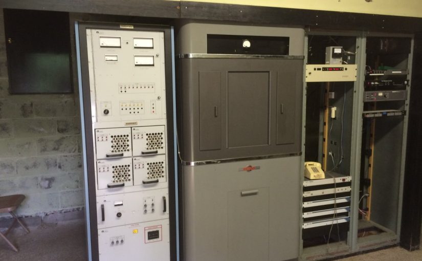
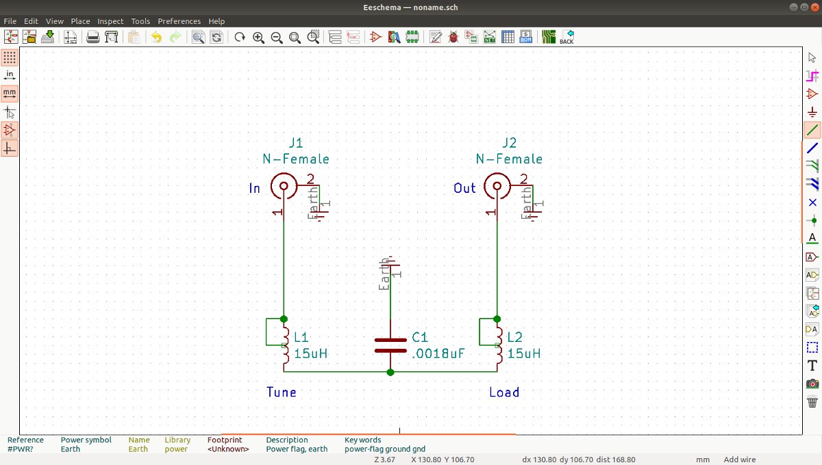
Objectively comparing those two systems, I can see that both systems have advantages and disadvantages. There are some common items required for both systems; a reasonably well maintained transmitter plant, a newer solid state transmitter, and an antenna system with enough bandwidth so as not to distort the digital signal.

There are more receivers available for HD Radio, especially in cars. HD Radio MA3 is less configurable and therefore less likely to be misconfigured. There has been a lot of ink spilled in recent years about the declining number of radio engineers and the increased work load they are facing. Are there enough people with sufficient technical skills to implement and maintain even a basic all digital system? A topic for another post.

DRM30 is more flexible. Operating modes, protection modes and CODECs can be adjusted according to goals of station owners. There has been more testing done with all digital transmission of DRM30 using Medium Wave.

Are there enough reasons to allow a test of all digital Medium Wave DRM30 in the US?

Why not allow both systems and let the Software Defined Receiver decide?

References:

  1. HD Radio Air Interface Design Description Layer 1 AM Rev. G December 14, 2016
  2. Digital Radio Mondiale (DRM) System Specification, ETSI ES 201 980 V4.1.1 January 2014
  3. Digital Radio Mondiale DRM Multi-Channel simulcast, Urban and indoor Reception in the Medium Wave Band, Document 6A/73-E September 19, 2008
  4. Project Mayflower, The DRM Trial Final Report, BBC, April 2009
  5. Results Of DRM Trials In New Delhi: Simulcast Medium Wave, Tropical Band, Nvis And 26 Mhz Local Broadcasting, Document 6D/10-E March 28, 2008
  6. All-Digital AM Broadcasting; Revitalization of the AM Radio Service, FCC Fact Sheet, MB Docket Nos. 19-311 and 13-249, October 19, 2019

All Digital AM?

I have been reading, with interest, the saga of HD Radio on the AM (AKA Medium Wave) band. First question; if it goes all digital, will we still call it AM? Of course, there are other questions and concerns:

  • The proprietary nature of HD Radio, AKA MA3 or NRSC-5D as they are now calling it, is problematic. Xperi, the latest patent owner, currently (their word) has agreed to waive licensing fees for AM station owners who install their system. Is this a limited-time deal for early adopters or in perpetuity for all stations?
  • The NRSC-5D tests on WWFD, Fredrick, Maryland are hopeful, but as I pointed out before, it is one station with a well-functioning antenna system. Many AM antenna systems are defective either in design or due to deterioration. Is the FCC going to start policing the AM band again to cure these self-inflicted wounds?
  • Of course, the NAB wants zero oversight on the entire adventure. Under their proposal, small ownership AM stations would have a difficult time remediating interference issues from all digital co-channel stations by eliminating any required notification period, as proposed by the SBE.
  • The NAB also wants to nix a 1 Hz carrier frequency requirement, which would help with both the analog and digital interference issue, saying it would be too expensive. I disagree. In this day of universal GPS timekeeping, it would be easy to implement this on all modern transmitters, especially if they were already installing an HD Radio exciter.
  • Denis Jackson’s Radio World Article states that reliable coverage can be had out to 0.1 mV/m. This seems very, very optimistic given that ambient electrical noise (non-broadcast related) on the AM band is at very high levels and still climbing. Further, once the all-digital conversion starts, more and more co-channel digital interference will happen, likely cutting down that contour to a great extent. It works now but may not work later. These types of statements seem naive or perhaps disingenuous. Again, WWFD is one digital signal in a vast ocean of analog carriers.

While I am skeptical of some of the statements made in various articles and comments before the FCC, I do believe that converting the Medium Frequency band to all digital will have benefits. The BBC DRM tests carried out in 2007 (The Plymouth DRM long term trial) show that digital on MF can work. DRM has been implemented in various countries with good results.

Getting rid of the hybrid IBOC/Analog is a step in the right direction.

My concerns are the small owners who are still making a go of it on AM. Those guys still doing community radio and serving the public interest. If they choose to wait, are they going to get buried under a digital dog pile and then have to pay the full license fee later? Something like that might be the end for them.

HD Radio in and of itself is not the panacea for the AM band. Other things have to happen to make it work right. The SBE speaks extensively about ambient noise on the MF band. They are entirely correct. In addition, there are many, many AM stations that do not have compliant antenna systems. There are stations operating a DA-2 system full-time on the night pattern. There are stations operating a DA-2 full-time on the daytime pattern and power. There are stations that are supposed to turn off at night, which stay on 24/7. There are stations not reducing power to nighttime levels. The list goes on. Simply putting digital carriers on everything will not reduce station-to-station interference, especially at night.

I am cautiously hopeful that the FCC will look into the ambient noise problem, which simply cannot be over-emphasized. They would also need to re-invigorating the Enforcement Bureau. Since they closed down most of their field offices, it has been kind of a free-for-all out here.

More AM work

I have been working on an AM station lately.   WBNR signed on in 1959 and follows the now familiar AM trajectory; after making bank in the ’60s, ’70s, and ’80s, revenue declined, maintenance deferred, yada, yada, yada…

After a stint with a news-talk format, the station changed to “Real Country,” a few years ago.  WAT! Music on the AM? Actually, it is doing quite well. The perception is that AM sounds terrible and nobody listens to it.  The stock AM radio in my Subaru (made by Pioneer) sounds pretty good on AM.  I have noticed that when I first tune a station in, it sounds narrow-banded, slightly better than a telephone.  However, after a second or two, the bandwidth opens up and it can sound quite good.  I have also heard this station playing at several local businesses.  When we turn it off to do maintenance, the phone starts ringing.  Clearly, somebody is listening…

This station is part of a three-station simulcast.  The AM station to the north got rid of its directional antenna and added an FM translator a few years ago.  That has made a big difference.  Thus a translator was acquired for this station as well.

The translator was held up by an informal objection filed by Prometheus, Et. Al.  as part of a blanket filing against all new translator licenses by the LPFM advocate.  In any case, the Construction Permit has been on hand for a while, so the owner felt it was time to move forward with building out the new FM signal.

Hoisting the Shively 6812 antenna

Installing the single-bay Shively 6812 antenna on the side of one of the nighttime towers triggered some other things.  A bit of the deferred maintenance was addressed;  new stockade fences around all the towers replaced the original fences put up in 1988. Those original fences were falling down.

4 Tower antenna system, WBNR, Beacon, NY

The antenna system for WBNR is actually quite elegant, perhaps even beautiful.  A simple two-tower system for the daytime array and a separate two-tower system for the nighttime array.  The nighttime towers are top-loaded, adding about 30.7 degrees in electrical height.

The far tower
The far tower

The CP for the translator required some extra steps because of the mounting on the night tower of the AM array.  Before and after impedance measurements need to be taken on the tower in question.  Another requirement of the CP, is a set of before and after monitor points need to be taken.

WBNR tower, with translator antenna side mounted at 390 feet AGL
WBNR tower, with translator antenna side mounted at 381 feet (116 Meters) AGL

While I was measuring the base impedance, I decided to measure all the towers instead of just the nighttime tower that has the translator antenna mounted on it.  This is a good point of reference if any problems arise in the future.  Often, this information can be found in the technical paperwork from the original license application.  Those files can be a treasure trove of information.  Unfortunately, it appears that a good portion of the original paperwork is missing.

WBNR tower #1 Antenna Tuning Unit

The Phasor and ATUs are a late 80’s Harris product.  They are actually in remarkable shape, all things considered.  All of the RF contactors are Harris HS-4P motor-driven units.  They are rated at 30 Amps, RF-RMS.  I don’t think that they are supported by GatesAir.  I have a small stock of spare finger stock and contact bars.  I suppose, if I had to, I could make or adapt parts to repair.

Looking at the base currents and the base current ratios for both the day and night patterns (base current ratios are on the station license), the tower impedance has changed very little over thirty years. That is good news, especially with those 215-degree-tall nighttime towers.

The WBNR license application did contain an overall system diagram showing the Phasor and all the ATUs.  It did not contain any component ids or other information.  I scanned that in, created a vector graphics file, and expanded it to a 24 x 36 inch size.  I was able to fit all the component values and other information on the diagram.

Schematic diagram WBNR day/night antenna systems

The other issue is the monitor point descriptions.  They include statements such as “Point is marked with yellow and white paint on a tree,” or “In the northeast corner of the Texaco research facility parking lot.”  Those references are long gone and I would prefer to use a set of GPS coordinates.  Using the topographical maps from the proofs, I found each monitor point and then recorded a set of GPS coordinates for each.  In the future, they will be much easier to find.  If anyone is still doing monitor points, I would recommend this method.

Yet another problem; the phasor control system was damaged by lightning. The overly complicated Harris Phasor control card was replaced with something more straightforward and reliable.   I designed a simple set of relays, one for daytime and one for nighttime, to change the antenna system over.  The transmitter interlock goes through the relay contacts, so the transmitter PDM is killed while the power changes.  Tally back from each of the towers is handled by a set of relays for each pattern, which is also interlocked with the transmitter.  All of this prevents the RF contactors from switching hot, something that has caused some damage in the past.

W243EM is 100 ERP watts, non-directional with a 1 bay Shively 6812-1R antenna installed at 381 feet (116 Meters) AGL on one of the nighttime towers.

The transmitter is a BW Broadcast TXT-600.  The power calculation is as follows:

ERP 100 Watts = 50 dBm
 
System gains and losses:
 
Transmission Line loss, 500 feet (152.4 Meters), RFS LCF78-50JA =  -1.75 dB
Isocoupler loss, Kintronic ISO-170-FM = -0.8 dB
Antenna gain, Shively 6812-1R = -3.39dB
 
Total system losses and gains: -5.94 dB
 
TPO: 55.94 dB or 393 Watts
 
With all that work completed, the license application was filed to cover the construction permit.  Once that was accepted by the FCC, program test authority was granted and the transmitter was turned on.  Hopefully, with the translator on the air, the perceptions regarding listeners will change and the station can bill more.
 
I really enjoy working on Medium Frequency antenna systems.  I don’t know why, but antenna systems in general are always fascinating to me.

BE AM tuning network

Occasional reader Scott asked for a picture of the inside of a BE AM output tuning network.  I figured it might be helpful to make a short post about it.

These things are pretty simple; a T network with a capacitive leg to ground.

BE AM Output tuning network

This particular unit is for 1230 KHz.  I believe the capacitor is frequency determined and they may also use larger inductors for lower frequencies.

BE AM output tuning network schematic

The inductors are Kintronic LV-15-20 (15uH 20 amp) and the capacitor is 0.0018 uF CDE 6KV 5.6 amp.

The issue with this particular unit is dirt.  The inductors have round metal plates that roll along the inductor coil to make the variable inductor tap.  Dirt has accumulated on the coil turns and on the inside of the plates.  This, in turn, causes arcing anytime the Tune or Load controls are moved.  A thorough cleaning should take care of the problem.