Status of AM revitalization

It has been about five years since the AM revitalization initiative was first proposed by the FCC and about five years since the first rules changes took place.  Those rules changes included:

  1.  FM translators for AM stations
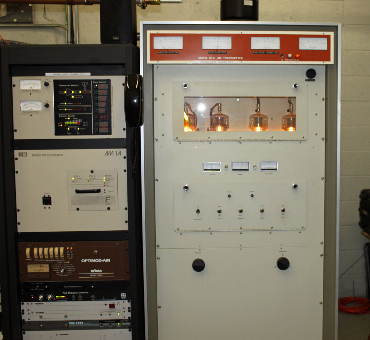
  2. Allowing stations to use MDCL (Modulation Dependent Carrier Level)
  3. Changing some of the antenna radiation efficiencies requirements
  4. Changing some of the allowable interference towards other stations requirements
  5. Loosening some rules regarding proofs, MOM, nighttime coverage over the city of license, etc

Things that were not addressed:

  1. Receiver quality and technical advances
  2. Ambient noise levels on Medium Frequency (among other) bands
  3. HD Radio or any other digital modulation scheme

Things that were discussed then changed subsequently as a separate initiative:

  1. The main studio rule, which was eliminated for all broadcasting stations

What has been the net effect of these changes?  Has any of this revitalized AM radio?  The net effect has been approximately more of the same.  There have been many stations that have applied for and received licenses for FM translators.  Those stations, in most cases that I am aware of, receive some benefit of extra revenue because of this.  Stations with carrier power levels of 10-50 KW have taken advantage of MDCL technology to save some money on their electric bill.  Nothing wrong with that.

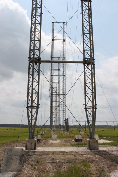
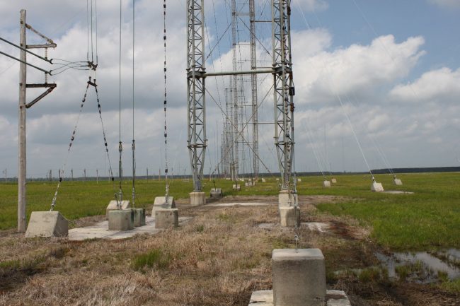
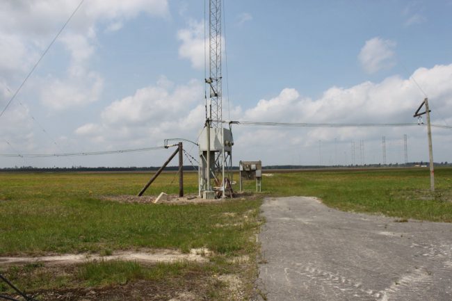
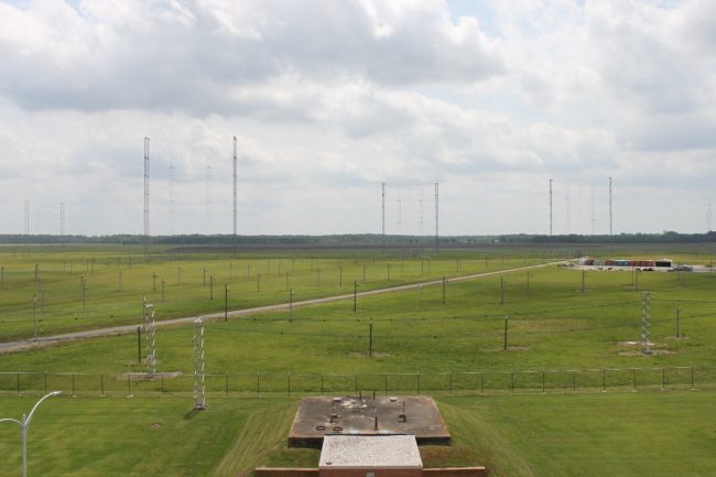
For stations that use a directional antenna, proofs of performance and other DA matters with the FCC have become slightly easier.  Medium Frequency (MF) directional antennas are very large, require a lot of land, are expensive to build, license, and maintain.  I know of several stations which have downgraded from a class B station with a directional antenna to a class D station with a single tower and greatly reduced nighttime power.   Those downgraded stations certainly benefit from an FM translator.

I have heard from more than one AM station owner who says after four years, they are going to “turn in their AM license and just keep the FM.”  I am sure that they are not informed regarding translator rules.  Perhaps, however, the FCC will allow this in the future; a sort of back-door commercial low-power FM station classification.

The AM band zenith occurred in November of 1991 when there were 4990 licensed AM stations in the United States.  As of June 30, 2018, the total stands at 4633.  That is a decline of 357 stations.  There are currently 90 AM stations listed as silent.  That represents a decline of approximately 9 percent or less than 1/2 of one percent per year.

The last number of AM stations actually transmitting HD Radio that I found was approximately 110, which differs from the iBiquity (and FCC) number of 240.  The FCC database includes stations that are currently dark or stations that were transmitting HD Radio at one time but have since turned it off.  Either way, it is a small percentage of licensed stations.  As of this time, AM HD Radio appears to be a non-starter.  In other parts of the world, Medium Frequency DRM seems to be doing well.  The difference seems to be that the DRM operation is all digital and the digital carriers have a much higher power level than that of the hybrid AM HD Radio being used here.

Of those 4633 standard broadcast stations, approximately 260 belong to iHeart radio, Cumulus owns approximately 120 and Townsquare owns approximately 80.   That accounts for 460 stations.  The remaining 4000 or so stations currently on the air are owned by medium-sized corporations or individual owners.  The reason for the distinction; I have noticed that large corporate owners tend to concentrate resources and effort on those licenses that will make the best return, e.g. FM stations.  Of course, there are a few exceptions to that trend, often in major markets.

Of those 4000 or so remaining AM stations, most seem to be treading water.  They are making enough money to stay on the air.  There are a few AM stations that are doing remarkably well.  Those are the ones with primarily local content.  The vast majority of AM stations are running some type of syndicated talk.  News/talk and sports radio are the two most common formats.  Conservative news/talk seems to be the bread and butter.  Liberal news talk has been tried, but none have succeeded.

Last May, the Supreme Court overturned the Professional and Amateur Sports Protection Act of 1992.  That federal law prevented gambling on outcomes of professional and college sports games.  With the overturn of that rule, individual states can now legalize sports betting.  It will be interesting to see what states allow legalized sports gambling and whether that has any effect on the various sports radio formats.  I can see where individuals and odds makers may want to get good inside information regarding team dynamics and so on.  The sports network that can furnish such information may be in a good position to carve out a niche.

Music can and does sound good on AM when it is done correctly.  There is a great misconception that AM fidelity is poor.  That is not necessarily so.  There are a good many AM receivers these days that have much better bandwidth than the previous generation receivers.  I am noticing that car radios in particular sound much better.  Yes, there are still problems with electrical noise and nighttime interference.  There are still technological improvements that can be made for analog AM on the receiver side.

In summary; the revitalization efforts have benefited some AM stations in some areas.  The truth is, that many AM stations have been let go for so long that there is no saving them.  Other AM stations that are still viable are making a go of it.  In nautical terms; there is six feet of water in the hold, the pumps are working and the ship is not sinking… for now.

VOA Site B, Greenville, NC

I took a brief vacation last week along the coast of North Carolina. It was relaxing and fun to be sure. I was also aware of and slightly curious about the Voice Of America shortwave site, a slight distance inland in Grimesland, NC.  Thus, I made arrangements to visit the facility on my way home.  Chief Engineer, Macon Dail, was gracious enough to give us the guided tour.  The facility is an engineering marvel.  The scale and complexity are enormous.  The entire facility is scrupulously maintained.  Many of the transmitters and other equipment have been upgraded to make them more functional.   I tried to take meaningful pictures, but in many cases, they simply do not do justice.

Edward R Murrow Transmitting Facility, (VOA Greenville Site B) Grimesland, North Carolina

Officially known as the Edward R Murrow Transmitting Station of the International Broadcasting Bureau, VOA Site B was constructed in 1961.  Six of the eight shortwave transmitters are original to the construction of the building.  The other two (BBC SK55 and AEG S4005) were added in 1986.  All of the dipole curtain arrays, rhombics, transmission line, and antenna switching matrices are also original.  A few brief statistics about this site:

  • Land area is 2,715 acres (1099 hectares).
  • Over twenty-six miles (forty-two kilometers) of 300-ohm open transmission line rated at 500 KW.
  • Sixteen dipole curtain arrays, average antenna gain 17 dBi.
  • Twenty rhombic antennas, antenna gain 15 dBi.
  • Two of the dipole curtain arrays can slew azimuth and take off angle.
  • Three Continental Electronics 420A 500 KW Doherty modulated transmitters.
  • Three General Electric 4BT250A1 250 KW high-level plate modulated transmitters.
  • One Brown Boveri Company (BBC) SK55C3 500 KW PSM transmitter.
  • One AEG Telefunken S4005 500 KW PDM transmitter.
  • The antenna switch matrix connects any of the eight transmitters to any of the thirty-six antennas

While we were there, both of the newer transmitters were on the air, running at 250 KW.  The GE transmitters are used as needed and the Continentals are rarely used due to age, difficulty to tune, change frequencies, and gross power inefficiency.

The station staff has, out of necessity, fabricated some very cool upgrades to the transmitters and facility.  The first of which is the alarm annunciator, which is based on a Star Trek (Original Series) sound scheme.  Once or twice I heard the bridge general alarm go off, followed by a female voice stating the problem: “GB8, OFF AIR.”

Chief Engineer’s office.  NCC-1701; no bloody A, no bloody B, no bloody C, and no bloody D

The GE 250 KW transmitters have been retrofitted with a computer-controlled auto-tune system for frequency changes.  The antenna switch matrix controller has been replaced by a PLC-based system.  As the transmitters are so old, many of the transmitter-specific parts need to be machined or fabricated locally.  The rest of the transmitter parts are stocked in a large parts storage room, all of which are meticulously labeled and tracked.  The floors are waxed and spotless, there is no dust on the horizontal surfaces, the workshop is clean, tools are put away, grass and weeds are cut, etc.  All of these little details did not go unnoticed and indicated great pride by the staff in the facility itself.

The heart of the facility is the control room which consists of four rows of equipment racks and a central operating position elevated above floor level.  Arranged around that are the eight shortwave transmitters in two long transmitter galleries.

VOA Site B control room

From this point, the operator can view all of the transmitters in the two transmitter galleries.

Operating position

Around the control operator are arranged a series of computer monitors showing various station function status.

Transmitter modulation and status indicators
Antenna Matrix status and control
VOA transmitter control and status (center)
Audio monitoring router

The equipment is installed into the equipment racks by type; one rack contains the frequency generators for each transmitter, the next contains first-stage power amplifiers, the next contains audio processors and modulation monitors, etc.

Equipment racks and Shift Supervisor’s  office
Transmitter frequency generators
Audio processors, modulation monitors and patch panels
Backup audio feeds

The audio comes from the VOA studios in Washington DC via satellite. There are Comrex Access links as a backup and the Gentner EFT-1000s are used as a backup to the backup.  Prior to 1995, an eight-hop microwave system covering the 300-mile (483 KM) distance was used.

GE 4BT250A transmitter with computer-controlled tuning system installed

The station staff has created a computer-controlled tuning system for the GE transmitters. Each transmitter can change frequency several times a day, during each frequency change, all of the transmitter stages need to be retuned. When done by hand, this can take several minutes to accomplish. The computer system uses follow pots and microcontrollers to set the tuning elements to specific values. They can be touched up by hand if needed. A frequency change can usually be done in less than one minute.

GE 4BT250A transmitter
Your humble author and CE Macon Dail discussing the auto-tune system
GE 4BT250A auto-tune modification
GE 4BT250A IPA tube and input tuning.

The 2nd IPA and PA input tuning work the same way. The copper sleeve slides up and down over the coil to change resonant frequency. The vapor-cooled tube sits inside the tub at the top, anode facing down. These tuning sections are a mechanical nightmare according to Macon. One of the reasons why VOA site A was closed down was due to the frequent frequency changes at that site causing excessive wear and tear on the old GE transmitters. This particular transmitter was being repaired; the staff was rebuilding a tuning network bypass capacitor assembly

GE 4BT250A transformer vault

The GE transmitter transformers still contain PCBs. The plate transformers are in the back, basically pole transformers, one for each phase. Primary voltages are 4,180 volts, and secondary rectified voltages are 12 KVDC (PA plate supply)  and 15 KVDC (modulator plate supply).

Hallway and maintenance access to back of GE transmitters
AEG Telefunken S4005 500 KW transmitter on the air

While we were there, the newer transmitters were in operation transmitting Spanish language programming to Cuba on 13,605 KHz and 11,930 KHz.  Currently, the Greenville site is broadcasting mostly Spanish language programming with some English, French, and Bambara language programming for Africa.

A fact that does not escape the notice of the staff.

VOA transmitter gallery, showing transmitters GB8 through GB4
Continental Electronics 420A 500 KW Shortwave transmitter control and metering panel

The three Continental 420A transmitters (GB-1, GB-2, and GB-3) are essentially a pair of 250 KW amplifiers combined. As these are Doherty power amplifiers, frequency changes are very difficult to effect. These transmitters spend most of their time in backup service.

Electrical distribution panel

The antenna matrix building is very impressive. Routing eight 250 or 500 KW transmitters to 36 different antennas takes a bit of doing. Mechanizing that setup is no mean feat. The pictures I took of the antenna matrix building do not show the size and complexity of the system.

Transmission line between transmitter building and antenna matrix building

For that, we need a satellite photo:

VOA Site B antenna matrix building

Basically, the transmitter building is in the lower left-hand side of the picture. The transmission line go over to the antenna matrix building (looks like rectangular ductwork), then runs all the way to the back of the building. Each antenna transmission line comes into the building and runs to the other side. Pneumatic arms then couple the transmitter line to the antenna line. This is all controlled by a custom-made PLC and controlled by the operator from the main operating desk.

Custom-made antenna matrix control system
300-ohm open transmission lines
300 ohm open transmission lines

Some of these lines are very long but have low loss due to the air dielectric. The most used antennas are the dipole curtain arrays.

Dipole curtain arrays

These consist of a series of broadband dipole antennas arranged side by side and stacked three or four high. behind those antennas is a reflector screen. There are two curtain arrays that are slewable. The dipole antenna’s phase relationship to each other can be changed to adjust the takeoff angle and azimuth, thus giving optimum coverage to the targeted area.

Close up curtain array

In this picture, the dipole antennas are to the right. Behind them is the reflector screen, and behind that is the antenna feed system. Each antenna feed goes through the reflector screen to the center of the dipole antenna.

Each array requires four towers to support it.

Curtain dipole array supporting towers
Remote Antenna Switch.  Allows two antennas to use one transmission line.

The entire antenna field is viewable from an observation platform on the main building

Observation room
Entrance gate and slewable curtains in the background
Curtain arrays

The entire facility is very impressive. The truth is, I could have spent several more hours there, but I know that people have jobs to do and I felt that I had taken up enough time. We often forget in this country that not everyone in the world has access to the internet. Shortwave broadcasting has a long reach and is not subject to government-controlled firewalls or other forms of electronic censorship. Currently, the Greenville site is broadcasting mostly Spanish language programming with some English language programming for Africa. There are many areas in the world that are in political tension right now, some startlingly close to home. Places like Brazil, Argentina, and Venezuela have been in the news lately. I do not see a time when these long-reach broadcasting services will not be needed. Becoming a welcome source of good information for those affected people is good for brand USA. It would be money well spent to invest in a couple of new Continental 419H (still made in the USA) DRM-capable transmitters for this facility. While the old GE and Continental units are great, the time may come when they are really needed but unavailable due to being down for repair.

Special thanks to Macon Dail for his time, knowledge, and patience.

Middle Aged Iron: Cetec/Bauer 701B transmitter

In service as a backup unit at WALL 1340 KHz in Middletown, NY:

WALL 1340 KHz, Middletown NY AM1A on air, 701B into test load

I believe the Cetec transmitter is from the early 70s. I wouldn’t really call it old, we have much older units in the field that are still in backup service.  WALL itself has been on the air since 1942 from this site. The tower out back was replaced in the mid ’90s and is 147 degrees tall. It broadcasts the “True Oldies Channel” and is currently owned by Cumulus, soon to be Townsquare.

Cetec 701B tube deck.  4-500As.
Cetec 701B tube deck. 4-500As.

The site is also home to sister station WRRV (92.7 MHz) which has a side mounted antenna near the top of the WALL tower. We are currently reconnecting the CCA transmitter as the backup for WRRV. That unit is also from the early 1970’s.

WRRV WALL transmitter site, Middletown, NY
WRRV WALL transmitting tower, Middletown, NY

Well designed circuit boards

Sometimes it is the little things that catch the eye.  When I was installing a Nautel transmitter recently, I was admiring the circuit boards used for the transmitter controller.  I have seen a few circuit boards that are functional, but leave a little to be desired in the form department.  Does it really matter?  Perhaps not, but often times those tiny, almost insignificant details come back to bite you.  Little things like having the voltage regulator pins correctly placed or putting a toggle switch on the correct side of the board.  I have seen both mistakes from another, well known transmitter manufacturer.

Nautel NV controller board

Anyway, these are a few photographs of some well designed, well laid out circuit boards.

Controller board, NV transmitter

This is the main controller board.

NV controller board surface mount components

Surface mount components.

NV controller board
NV controller board

Logic chips.

Nautel XR harmonic filter, part back part is the circuit board

Part of the harmonic trap for the XR series transmitters.

It really is the little things that make big differences.  A circuit board under a cover that few people will ever see may seem like a very small and insignificant detail, but I notice and admire these things…