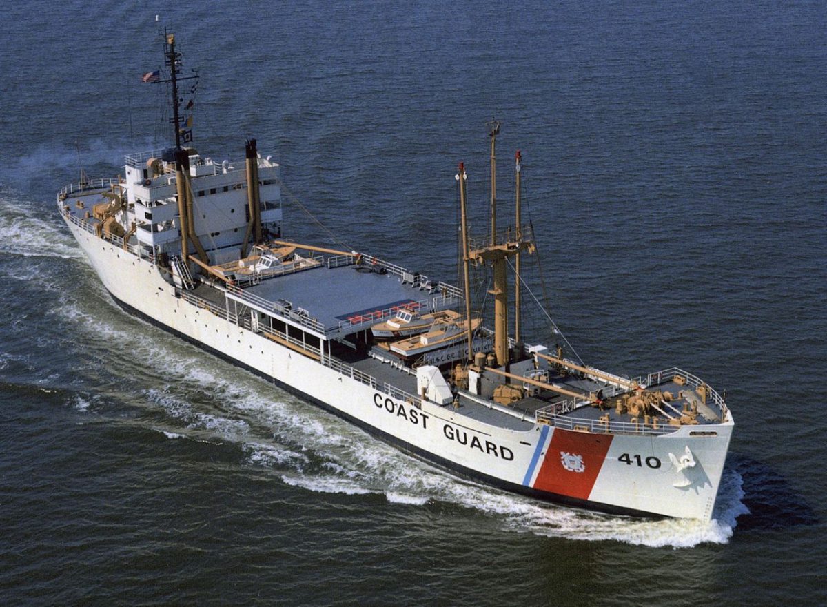
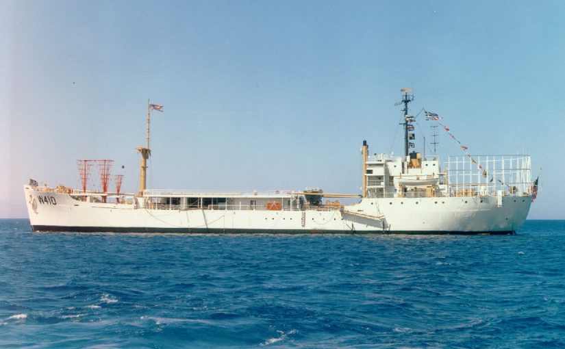
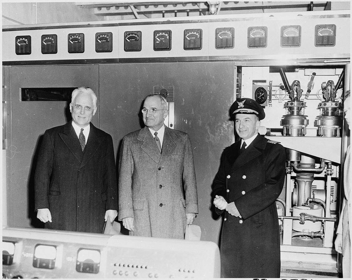
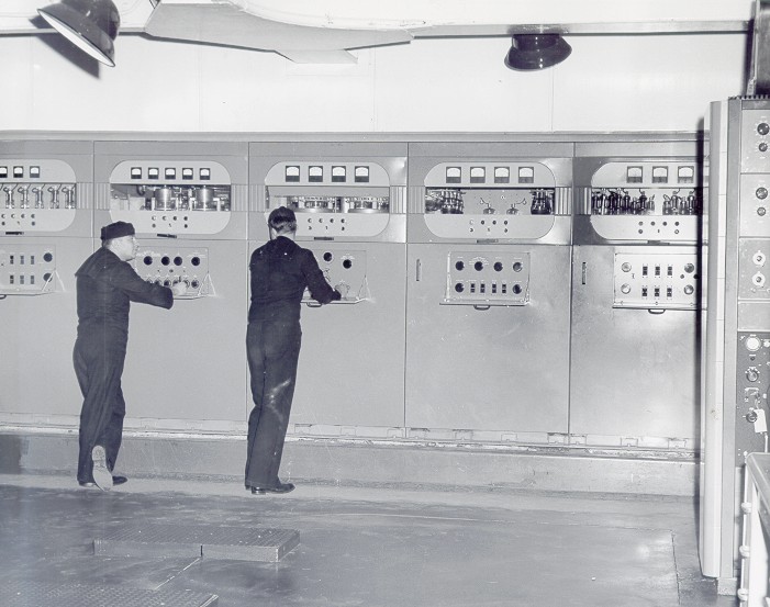
May 2012
M T W T F S S
« Apr    
 123456
78910111213
14151617181920
21222324252627
28293031  

Archives

Categories

Things that make you go Hmmmm? Part IV

The case of the blown fuse, or rather the blown up fuse:

Blown 10 amp fuse on Harris SX5 PA board

Blown 10 amp fuse on Harris SX5 PA board

F32 is blown to small bits and had to be vacuumed out of the bottom of the transmitter.  The reason why is the pair of MOSFETS connected to that circuit were shorted.  Of course, the reason for the shorting MOSFETS needed to be investigated.  What I found was on the under side of the PA board where the brass stand off attacked to the torroid combiner board, the nuts attaching the stand off to the combiner board was loose and there was a big arc mark.

I tightened everything up and replaced the MOSFETS, marking them with a pen in case they short again, in which case the drive section needs to be closely examined.

The Harris SX 5

I give you joy, the unmitigated joy and shear pleasure of the Harris SX 5 AM transmitter. This particular unit dates from 1984 and is installed at WUPE in Pittsfield, MA.   It has a few issues of late.

Harris SX 5 medium frequency AM transmitter

Harris SX 5 medium frequency AM transmitter

The first of which is the unbalanced or out of ratio condition of the PA current and voltage.  When changing power levels, the PA current and voltage are supposed to track together.  When they do not, it is an almost sure sign that one or several of the MOSFETS in the PA are shorted.  Shorted IRF-350 MOSFETS are indicated by blown fuses on the PA boards and should be replaced in pairs.  The reason for the damaged devices also needs to be investigated.  It is entirely possible that the site receives a lot of lightning, which can cause this damage.  It could also be heat related, as the site is not currently air conditioned.  The other possibility is under drive conditions.

The MOSFETS turn on and off at a rate of 1/(carrier frequency (hertz)) times per second.  If they are under driven, they will go full on and short circuit.  Minimum drive is 27.5 volts peak to peak, anything less than that is marginal and can lead to destruction of the PA devices.  Under drive indicates an issue with the oscillator, which has it’s own set of peculiar failure modes.

Since this is an older unit, all of the large electrolytic capacitors are also suspect and need to be replaced.  There are three power supply capacitors in the bottom of the transmitter, two 76,000 μF 40 VDC for low voltage and one 7500 μF, 350 VDC for high voltage.  The modulator section also has six 5100 μF 350 VDC capacitors, collectively known as “dynamite sticks” due to there explosive potential if installed incorrectly.

Harris SX 5 modulator section

Harris SX 5 modulator section

While replacing the dynamite sticks, I noticed this PDM pickup board has a whole burned through it.  This is a part of the modulator section and if it burned completely open, would likely cause all sorts of problems with this transmitter, likely spurs all around the dial, distorted modulation or perhaps overload and fail altogether.

Harris SX 5 transmitter damaged PDM pull up board

Harris SX 5 transmitter damaged PDM pull up board

I managed to fix it with a jumper between what is left of the circuit board trace and the capacitor mounting bracket.  I soldered the jumper to the board face and soldered the wire lug.  After scraping all the oxidized metal off of the capacitor mounting bracket, I attached with a screw. The board itself needs to be replaced, if it is still available from Harris, which it may not be as support for this transmitter was dropped in 2008.

Harris SX5 PDM pull up board temporarily repaired with wire jumper

Harris SX5 PDM pull up board temporarily repaired with wire jumper

The worst, and I mean worst possible situation with these transmitters is some type of control malfunction.  The control boards and oscillator are in that large vertical pull out drawer.  God protect and preserve the digital control and S and M boards, as they are a major headache to troubleshoot.  They have 7300 TLL (5 volt logic) that controls all functions and only little problem will cause the entire transmitter to shut down.

Other SX series transmitter tips can be found here.

I didn’t get to replacing the blown devices because of a looming electrical storm, which precludes working inside of transmitters.  I’ll get back there next week and finish the job.

Update: I finished the repair job today 8/24.  There were 16 blown MOSFETS on the PA boards.  I checked the drive levels on the input side of the RF torrid load resistors and it is with normal range.  I also found this snake in the bottom of the transmitter across the HV shorting bar.

Small grey rat snake, electrocuted by Harris SX 5 transmitter

Small grey rat snake, electrocuted by Harris SX 5 transmitter

Could have been chasing diner.  Overall, the site needs help.  The air conditioner is coming next week.

Harris SX 5 transmitter fully operational

Harris SX 5 transmitter fully operational

After repairs, the transmitter is back at full power and modulating +125% again.

Tube transmitters vs Solid State transmitters

I thought it would be interesting to do a comparison between the two types of transmitters, both AM and FM.  I have been doing this thing for 25 years and have quite a bit of experience working on all types of transmitters.  Some of the broadcast transmitters I have personally worked on over the years include:

  • Harris: FM-20H, FM-5G, HT-35, HT-10, HT-3.5, FM-25K, FM-5K, Z5-CD, MW-50A, MW-50B, MW-1A, MW-5A, BC-5H, SX-5, SX-1A, Gates 1
  • Broadcast Electronics: FM-5B, FM 3.5A, FM5A, FM30A, FM35A, FM30T, FM20T, FM10S, FM5C, FM1C, AM10A, AM6A, AM5E, AM1A
  • Continental Electronics: 816R-2, 814R-1
  • Collins Rockwell: 831F-1, 838E-1
  • Nautel: ND-1, ND-5, XL-60, V-40, V-10, V-7.5, NV-40
  • Gates: BC5P, BC1T, FM5B
  • General Electric: BTA-25
  • RCA: FM20ES1, BTA5J, BTA1-AR
  • CSI/CCA, Visual, Energy Onix, Bauer, McMartin, QEI, some Italian something or other, etc.  Various makes and models.

I think I have a fair amount of transmitter experience under my belt.  What I have found is that certain brands of transmitters are better than others, regardless of whether they are tube or solid state.  There are several differences in each type, obviously.  As to some blanket statement about which is better, solid state or tube, I don’t have one.  My statement would be “It depends.”

Tube transmitters are more rugged and will take more abuse than a solid state unit. Things like heat, lightning, EMP, mismatched antenna won’t phase a well designed, well manufactured tube transmitter.  On the other hand, they are less efficient AC to RF, have higher B+ voltages, have hard failure modes, and are more difficult to linearize, if that is required for some reason.

Solid state transmitters are more broadbanded, easier to change frequency, they have soft failure mode due to redundant amplifiers and power supplies. The voltages are lower, thus they are safer to work on.

Here is a complete list of advantages and disadvantages of each type:

Attribute Tube Solid State Comment
Ruggedness Very rugged, able to take heat, EMP, lightning, mistuned antenna, poor operating environment, etc Not heat tolerant, lightning and EMP can damage MOSFETS, switching power supplies sensitive to AC mains issues Advantage: Tube
Electrical Efficiency Less efficient More efficient Advantage: Solid State, however efficiency gain can be wiped out due to larger air conditioning requirement
Failure mode Hard, most often Soft, most often Advantage: Solid State, failure of a single module or power supply generally will not take unit off the air
Frequency agility Difficult Easy Advantage: FM Solid state transmitters can easily be moved.  AM transmitters still require extensive retuning.
Re-occurring cost More Less Advantage: Solid State, as tube changes are required every two to three years
Maintenance Same Same Advantage: neither
Servicing Requires skilled engineers to service and trouble shoot Modules and power supplies are often hot swappable and returned to manufacture for repair Advantage: Solid State, however either type requires occasional measurements with specialized test equipment
Servicing safety High voltages, contact will be fatal Lower voltages, but can still be fatal Advantage: Solid State
Redundancy Low High Advantage: Solid State, multiple power amps and power supplies give solid state units more redundancy
Cost Less More Advantage: Dependant on TPO, Higher powered solid state transmitters are much more expensive than there tube type counterparts
Availability Good used market, some new FM transmitters still being built Good new and used Advantage: Tube
 Reliability  Dependent on brand  Dependent on brand  Advantage: neither

For some reason, the latest Broadcast Electronics tube type transmitters seem to have very long tube life.  I installed an FM20T at WYJB in Albany, New York,  in early 2001 and it is still on the original tube, some ten years later.  Same can be said for the 2005 FM20T and FM30T installation at WHHZ/WKZY, Gainesville, Florida.   Those tubes shows no sign of giving up anytime soon.  I don’t know if that is an unusual trait of the transmitter or that particular tube.

WKZY, Gainesville, Florida

WKZY, Gainesville, Florida

The above comparison seems to heavily favor a solid state transmitter.  As a general rule, brand new solid state transmitters both AM and FM have advantages in almost every category except high power FM transmitters, where tube types still make sense.  From a used transmitter standpoint, there is nothing wrong with a tube type transmitter, provided it has a solid state IPA.  I have noticed the 4CX250B driver tubes most often used in FM IPA stages have markedly reduced reliability of late.  I would also tend away from transmitter makes and models where the manufacture is no longer in business or no longer supports the product.

Transmitter trips main breaker

Received a call last night, after a particularly bad thunderstorm, that WGHQ in Kingston, NY was off the air.  Earlier in the day, the transmitter had tripped the main breaker after a thunderstorm.  I arrived at the transmitter site and found the breaker tripped again.  Once the breaker was reset, the transmitter came back on and ran without any overload indications.  The transmitter is a 10 year old Nautel ND-5.

WGHQ Nautel ND-5 transmitter

WGHQ Nautel ND-5 transmitter

I was thinking breaker fatigue as the breaker is the original 1960 breaker installed when the building was built.  I reset the breaker and turned the power output down to 3 KW, thinking the reduced load might not trip the breaker until we could get a replacement.  The transmitter was on the air running as I was about to lock up and go home when I heard, but more felt through the floor, a THUMP! There I stood and watched the transmitter go dark.

At least it happened when I was there looking at it.  Because of the lightning, I was thinking something in the output network.  I reset the breaker and once again, no faults and the transmitter came back on.  Strange.  Obviously some sort of power supply issue.  Here are the clues:

  1. The B- voltage was right where it should be at 72 volts.
  2. All other readings, reflected power, forward power, power supply current are normal before and after the breaker trip
  3. No fault lights
  4. The service panel breaker, which was tripping, is rated for 70 amps, the transmitter front panel breaker which did not trip, is 50 amps.

The Nautel factory rep was thinking either breaker fatigue or the big transformer in the base of the transmitter had gone bad.  According to him, no one had ever heard of a transformer going bad in these transmitters, which makes a certain amount of sense.  Unlike a tube transmitter, which steps the B+ voltage up several times, these transmitters reduce the B- voltage by about 2/3rds or so.  With a step up situation, a surge would be multiplied many times and could very easily punch a hole in the transformer’s secondary winding insulation.  I have, in fact, experienced this on at least two occasions.

That leaves the wiring between the transmitter and the service panel.  I double checked the panel breaker with my volt meter to ensure that the voltage was indeed off.  Then I removed each phase from the connection lugs in the transmitter and tested the wire to ground with my Fluke 77 DVM.  Sure enough, two of the phases showed resistance of 1.2 and 1.7 MΩ to ground were it should have been infinite.  Further, when I took the cover off of the service panel, I found a dead mouse.  Unfortunately, I didn’t have any #4 THHN and all the home improvement stores were closed by that time, so it had to wait until morning.

The thunderstorm seems to be a coincidence.

After we pulled the wire out of the conduit, we found this:

mouse chewed feces encrusted electrical cable

Mouse chewed feces encrusted electrical cable

It is a little hard to see, but that shiny spot is copper.  The cable jacket is chewed back quite a ways and the entire thing is encrusted in mouse feces and urine.  I love to work on stuff like this.  LOVE IT!  Hantavirus, here we come!  That reminds me, I need to get some of those blue latex exam gloves and throw them in the truck…  Anyway, far back in the conduit running through the concrete floor where it bends to go up to the service panel, the mice apparently had a nest.  They got into the conduit under the transmitter, where it transitioned from 3 inch rigid to 1 1/4 inch flexible metal without benefit of a junction box or proper fitting.

We pulled new copper conductors in and installed a proper junction/transition between the 3 inch and 1 1/4 inch conduit.  The service panel was also missing several knockouts of various sizes, which were sealed with knockout seals.  The transmitter was back on the air at full power about 16 hours after it went off.  Unfortunately, the station has no back up transmitter, so they were off for that period of time.  Perhaps now they will look into a backup transmitter or at least an exterminator, but probably not.

WCKY transmitter site tour

This is of interest because of the GE BT-25-A transmitter footage.  I do not know the serial number of the WCKY BT-25-A transmitter, but it is looks identical to the old WPTR BT-25-A unit which can be seen in this post.  As I stated in that missive, I have not heard any transmitter before or since, that sounded as good as this unit.  They were really engineering marvels, even in 1999 when this video was shot.

No doubt the MW-50 (no letter) and particularly the DX-50 transmitters are more efficient. In this day and age when many AM stations are just scraping by, over paying for utilities is not an option. I noticed the Harris MW-50 transmitter with the PDM drawer open. That brings back memories too, those PDM boards where a pain in the rear, as I recall.

Donating old equipment

There is a propensity among radio engineers to save old equipment. Sometimes I look at something and think, “Man, that cost a lot of money ten or twenty years ago.”  Truth be told, much of what is saved will never be used again.  This equipment should be scraped or donated to someone who might find it useful.  One thing that is most appreciated by Amateur Radio (AKA Ham) operators are old 1 KW tube type AM transmitters.  Ham operators love these things, and with good reason.

A fair amount of repair work, some cleaning and a bit of reworking will turn what might have been a useless dust collector into a 160 or 80 meter AM rig and with a good story to boot.

Personally, I’d rather see a Gates BC1T or RCA BTA1R off to a new home than off to the scrap yard.  To that end, today we unloaded the BC1T at WLNA to a willing ham.  This particular transmitter had last run in 2001 or so and was used as a spare parts supply for other BC1T transmitters owned by the same company.  There was no way it would ever work again and truth be told, it really wasn’t needed any longer anyway.  Since the Harris MW5B was replaced as the main transmitter by a BE AM6A, the backup transmitter was never used.

Gates BC1T transmitter

Gates BC1T transmitter

John Aegerter, a frequent commenter on this blog, drove all the way from Madison, Wisconsin to pick it up.  Prior to pick up, I removed all of the tubes, transformers, crystals and glass envelope time delay relays.  I packed up the glass objects in a box.

Gates BC1T tubes, transformers and spares

Gates BC1T tubes, transformers and spares

There were several spare tubes and parts which are no longer needed.  These went with the rig, along with what ever manuals I could find.

Gates BC1T loaded into pickup truck

Gates BC1T loaded into pickup truck

The transmitter was then loaded into the back of a Dodge Ram 2500 pickup truck and tarped for it’s trip back to Wisconsin.

The burned contactor fingers

This is a set of burned contactor fingers on a Harris HS-4P 30 amp RF contactor:

Harris HS-4P RF contactor

Harris HS-4P RF contactor with burned finger stock

The back story is this:

The contactor in question is at the base of Tower #3 of the WBNR (1260 KHz, Beacon, NY) antenna array.  This is the tallest of all the towers, at 405 feet.  As such, it gets struck by lightning often.  There was at least one occasion where one of the inductors in the ATU got “sucked in” due to the huge magnetic field of a high current strike.  It is not at all surprising to me to find other component issues in this ATU.  Because of the burned contacts, I’d suspect that the station was switching modes under power, but I didn’t see that happening today.

The problem manifested itself in very high SWR after changing over from day pattern to night pattern.  This did not occur every time, in fact, it only occurred once in a great while at first.  Then, over the last couple of months it began occurring more and more often.  Since the snow drifts are now down to a manageable six to eight inches, it was a good day to go out and do some exploring.

First of all, I put the station into night time mode just to confirm that there is still an issue.  The transmitter, a Broadcast Electronics AM1A showed very high SWR and carrier fold back.  Left it in night pattern, but turned it off and took a walk, not a drive, to Tower #4 which is all the way at the bottom of a hill, near the old City of Beacon landfill.  I figured that I would check that one first, then look at Tower #3 on the way back.  When I got to Tower #3, I found the issue right away.

Fortunately, I was able to salvage a set of contact and contactor bar from another relay in the same ATU that was not using them.

Burned RF contactor bar

Burned RF contactor bar

The night pattern is only 400 watts, but these are tall towers, 225 degrees, therefore current and voltage are high at the base.  In fact, the slightest change at the base of the night time towers will greatly upset things.

Burned RF contactor fingers

Burned RF contactor fingers

Harris HS-4P contactor repaired

Harris HS-4P contactor repaired

This is the repaired contactor.  I will say, the EF Johnson RF contactors are easier to work on.  Those are the ones with the big rocker bar across the top and two solenoids on either side.  All of the wiring, status switches and contacts are exposed and easy to get to.  This one, not so much.  This is the BE AM1A transmitter

Broadcast Electronics AM1A transmitter

Broadcast Electronics AM1A transmitter

It is not a bad unit, compact, sounds good, reliable, etc.  In order to work on the power supply or anything in that top cabinet, the whole thing needs to be removed from the rack and taken down.  I suppose that is my only gripe about the thing.

Continental Shortwave Transmitters

I started my radio career working in HF radio, albeit somewhat different than broadcasting.   I enjoy the long distance aspect of HF communications and there is something about the high power shortwave (HF) rigs that interest me. This is a video of a Continental 418E HF transmitter. The carrier power is 100 KW capable of 100% modulation, when means peak output power is 400 KW. This particular model has a solid state modulator, which is in the cage where the guy is walking around. From the video, it would appear they had several blown fuses in the modulator section. The fuses protect the individual IGBTs in the modulator.

This is an older transmitter that is getting upgraded to a 418F. The heavy cable is the connection between the solid state modulator and the RF final section. Depending on modulations levels, it carries around 33 KV.

From the Continental Electronics website that details the SSM unit:

The modulator consists of 48 series connected modules which are switched on or off to provide the high voltage DC and the superimposed high level audio voltage. The switching is accomplished with Insulated Gate Bipolar Transistors (IGBT). A low pass filter follows the series connected modules which removes the switching signals and allows the DC and audio signals to pass to the RF amplifier. Because each of the modules is either in full conduction with very low loss, or turned off, again with very low loss, the overall modulator efficiency is in excess of 97%.

A full description of the SSM is on the Continental Electronics SSM website. It is an interesting read, including the description of the 12 phase transformer setup.

Finally, a video of the VOA transmitter site in Greenville, NC.

This is part 4 of 5, if one wanted to, one could click through to Youtube and watch the rest of them. The VOA stuff is, as the transmitter engineer notes, 1950′s technology. No solid state modulators in these rigs. Those are some old transmitters, still in service and likely to remain that way until the VOA closes that site down, some point in the future.

Like their FM counterparts, Continental HF transmitters are the gold standard when it comes to high power tube transmitters. Sadly, they no longer make transmitters for Standard Broadcast (AM MW).

Milwaukee's oldest radio station

WISN 1130 AM has been on the air since 1922, although not always with those call letters.  In an interesting twist, the license was granted to the local newspaper, the Wisconsin News and the Milwaukee School of Engineering.  Initially, both entities were programming the station, however, by about 1925, the newspaper was responsible for programming and the engineering school was responsible for technical operations.

In 1941, the station increased power from 1,000 watts to 5,000 watts and added night time service.  This is a series of pictures from that time period.

WISN night time allocation study

WISN night time allocation study

Back in 1941, night time interference was taken seriously.  The night time allocation study (on 1150 KHz, WISN’s former frequency) includes co-channel stations in the US, Canada, Cuba and Mexico.

WISN night time allocation ma

WISN night time allocation ma

The array consisted of four Blaw-Knox self supporting towers in a rectangle.  Notice the lack of fencing, warning signs and the like around the towers.

WISN antenna array

WISN antenna array

From the front of the transmitter building

WISN transmitter site, 1941

WISN transmitter site, 1941

The site looks well designed, no doubt manned during operation, which at the time would likely be 6 am to midnight except under special circumstances.   Most of these old transmitter sites had full kitchens, bathrooms, and occasionally a bunk room.  The transmitter operators where required to have 1st telephone licenses from the FCC.   There is only one manned transmitter site in the US that I know about; Mount Mansfield, VT.  There, WCAX, WPTZ, WETK, and VPR have their transmitters.

WISN RCA BT-5E transmitter, 1941

WISN RCA BT-5E transmitter, 1941

The WISN RCA BT5E transmitter looks huge for that power level.  Back in the day when AM was king, these units were designed to stay on the air, no matter what.  I don’t know too much about this model transmitter, but if it is like other RCA/GE models from the same era, it has redundant everything.

RCA AM antenna monitor

RCA AM antenna monitor

Old school antenna monitor.  I have never seen one of these in operation, however, as I understand it, the scope was used to compare the phase relationship of each tower against the reference tower.

These pictures are of the WISN 1150 array was it was in 1941.  Since then, the station has changed frequencies to 1130 KHz and increased power to 50,000 watts daytime/10,000 watts night time.  The daytime array consists of six towers and the night time array has nine towers, all of which are 90 degrees.

Special thanks to John A. for sending these pictures along.

The Nautel ND-5 transmitter

This transmitter is about 10 years old. In ten years of service, there have been no failures.  Not one transistor has gone bad.  It is connected to a three tower directional array on 920 KHz.

WGHQ Nautel ND-5 transmitter

WGHQ Nautel ND-5 transmitter

Sadly, this model transmitter is no longer made.  They were built like tanks, heavy gage steel cabinets, well designed, well grounded circuit boards.

It is dirt simple; RF power MOSFETS on drawers, combined and tuned with the output network.  A power supply, exciter and simple control logic and nothing else.  No serial port to plug a computer into, no ethernet ports, no digital read outs, fancy efficiency optimizing computers, etc.  In the mean time, it does what it is supposed to do, stay on the air.

I was reading, with interest, the idea of “energy star” transmitters.  I think that good radio station engineers already take the electrical efficiency into account when buying a new transmitter.   That being said, electrical efficiency is not the only measure of efficiency an engineer should be considering.  Reliability, redundancy, and repairability must also be considered.  If the station spends an inordinate amount of time on the old back up transmitter while the new, super efficient main transmitter is off line is counter productive.  Not to mention the time wasted trouble shooting which could be better spent on something else.

Our Sponsors

Translate

Chinese (Traditional)DanishFrenchGermanItalianJapaneseRussianSpanishVietnamese

Axiom


Congress shall make no law respecting an establishment of religion, or prohibiting the free exercise thereof; or abridging the freedom of speech, or of the press; or the right of the people peaceably to assemble, and to petition the Government for a redress of grievances.
~1st amendment to the United States Constitution

Any society that would give up a little liberty to gain a little security will deserve neither and lose both.
~Benjamin Franklin

...radio was discovered, and not invented, and that these frequencies and principles were always in existence long before man was aware of them. Therefore, no one owns them. They are there as free as sunlight, which is a higher frequency form of the same energy.
~Alan Weiner

Everyone has the right to freedom of opinion and expression; this right includes the freedom to hold opinions without interference and to seek, receive and impart information and ideas through any media and regardless of frontiers
~Universal Declaration Of Human Rights, Article 19

Free counters!