Transmitter repair

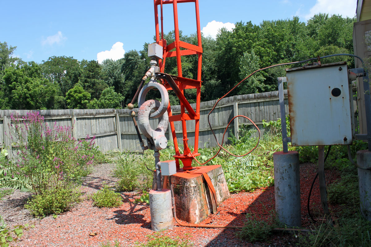
Sometimes it is obvious and relatively easy, other times not so much.  This summer we have had wave after wave of afternoon thunderstorms.  It is almost like living in Florida; almost, but not quite.  Anyway, with the storms occasionally comes some lightning damage.  At most of the transmitter sites we service, every step has been taken to ensure good grounding and adequate surge suppression.  This is especially true of sites that have been under our care for a few years.  Even so, occasionally, something gets through.  After all, those five-hundred-foot steel towers do attract lightning.

Broadcast Electronics AM5E output tuning section

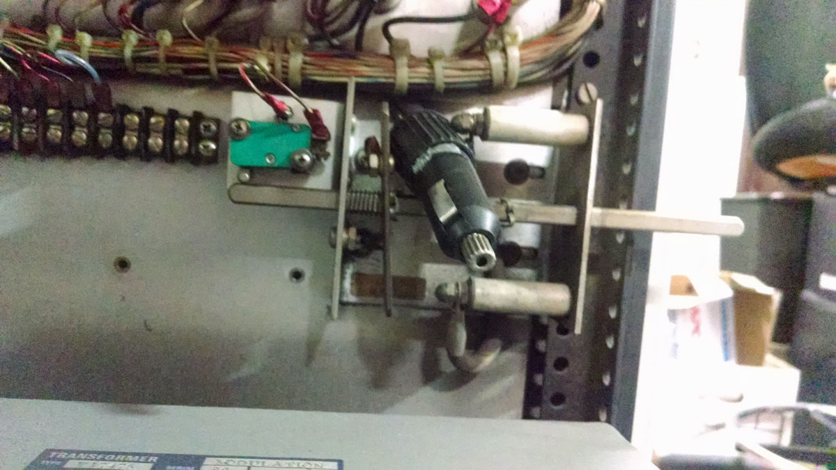
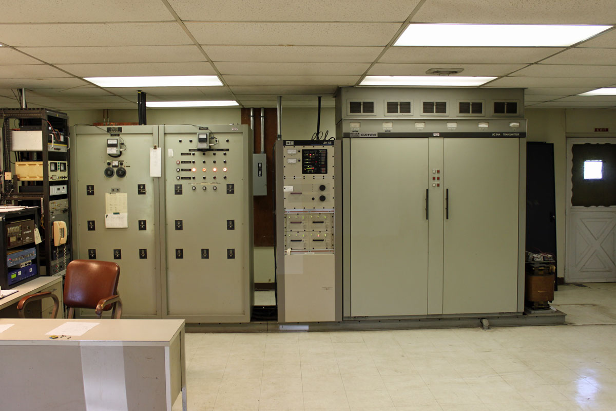
This is the output section of the BE AM5E transmitter at WROW.  The transmitter got pretty trashed; a bad PA module and power supply and this capacitor in the output section.  This particular transmitter is 14 years old and this is the first major repair work we’ve had to do it.

Broadcast Electronics AM5E output tuning capacitor

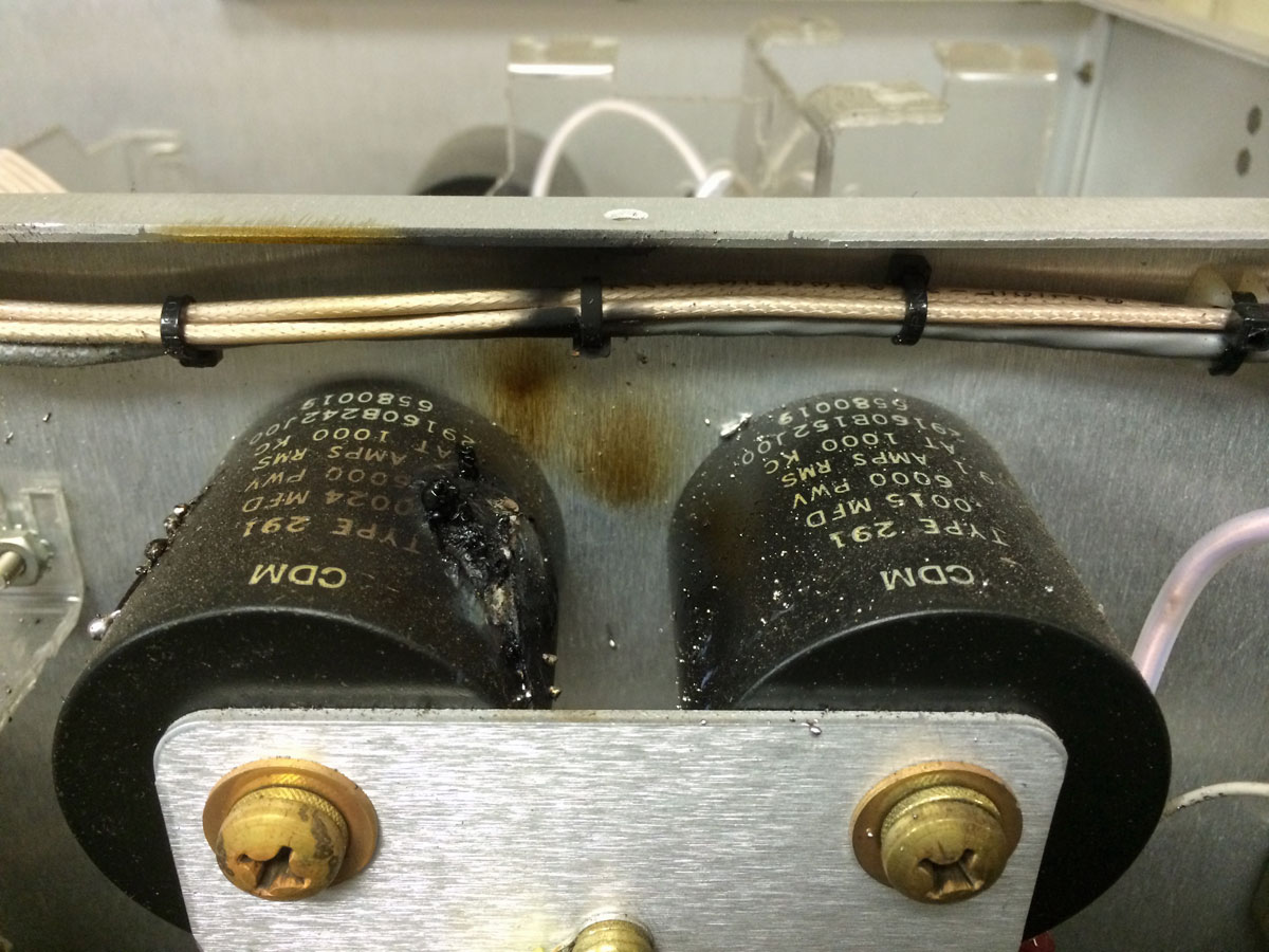
The capacitor was fairly easy to change out.  As a general precaution, both capacitors were changed.  There was a spare PA module and power supply on the shelf, thus the transmitter was returned to full power relatively quickly.

Broadcast Electronics AM5E output forward and reflected power meters

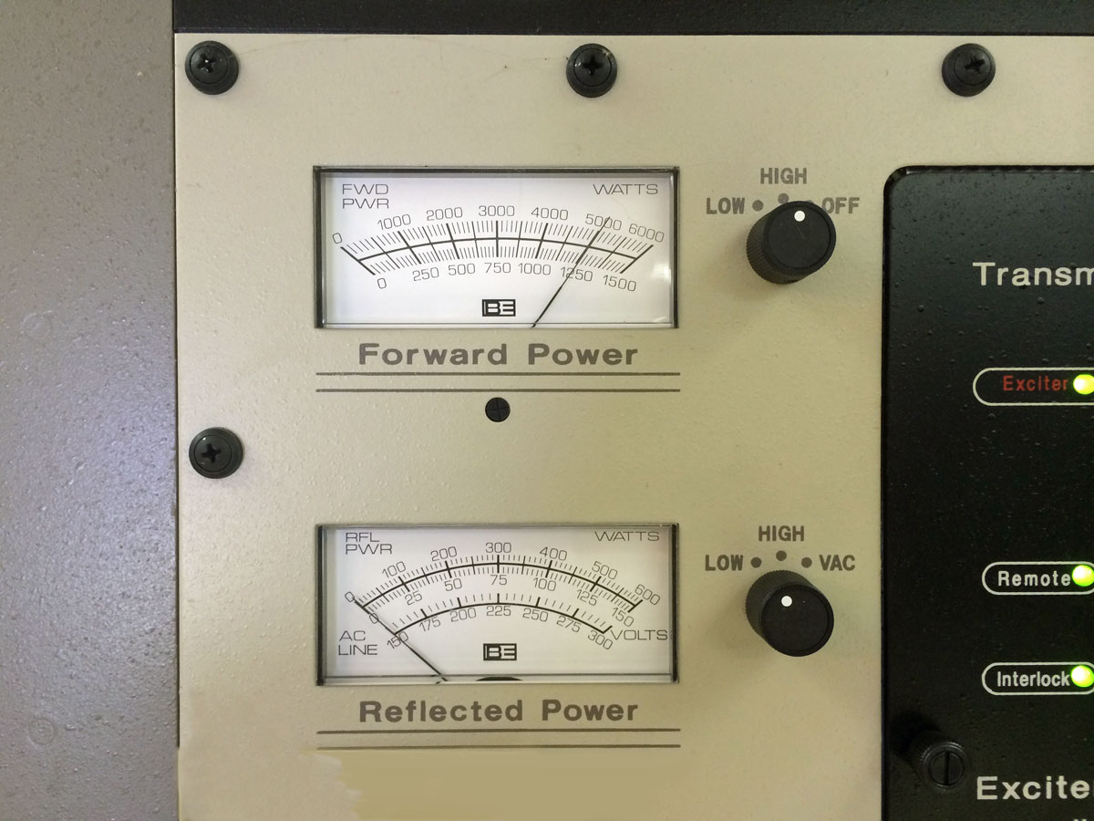
The rest of the antenna system and phasor were inspected for damage, a set of common point impedance measurements taken, which showed that no other damage was sustained.

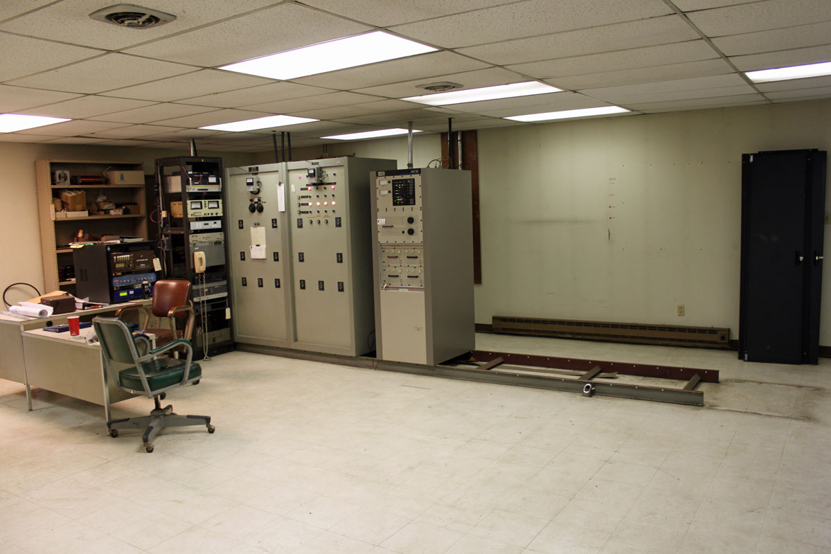
Next, the 30 year old Harris SX2.5 A transmitter at WSBS.  This failure was slightly more exotic; the transmitter started randomly turning itself off.  The culprit, in that case, was this:

Harris SX2.5 remote control interface bypass capacitor

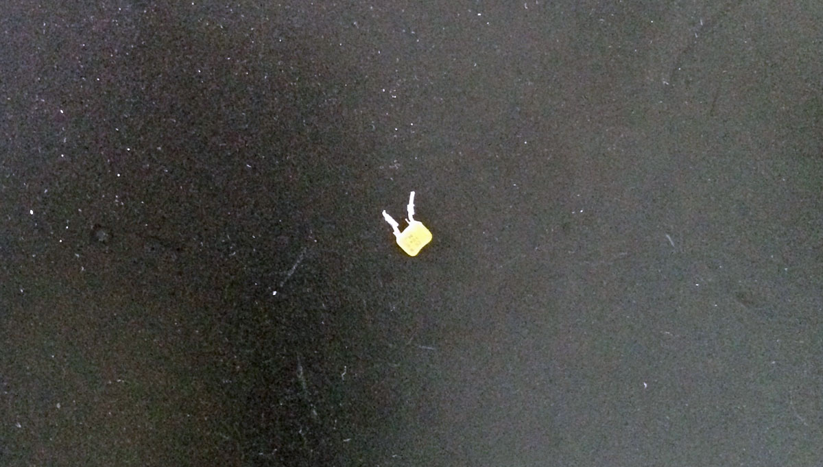
Literally, a two cent part.  The transmitter remote control uses optoisolators.  The inputs to these opto-isolators are RF bypassed to ground on the back of the “customer interface board.”  After determining that the remote control was not malfunctioning, it was down to either a bad opto-isolator or something really silly like a bypass capacitor.  This capacitor was on the ground side of the remote off terminal.  It shows short on the capacitance meter and 4.1 K on the ohm meter, just enough to randomly turn the opto-isolator on and shut down the transmitter.  Being a Harris transmitter, removing and replacing the “customer interface board” was no easy matter.  Overall, it took about three hours to find and repair this problem.

Engineer Killer

That was the title of the email with this photo attached:

Disabled high voltage shorting bar, Collins 820D-2
Disabled high voltage shorting bar, Collins 820D-2 AM transmitter.  Courtesy Pete Partinio

That seems about right.

For many, many reasons, this is a bad thing to do.  First of all, the shorting bar is the last point of discharge for the high-voltage power supply.  When all else fails, this is designed to route the 3,500-volt plate supply safely to ground.  Having a stray 3,500 volts floating around inside a transmitter is never a good idea.  Fortunately, it was spotted and removed before anything bad happened.

Secondly, it looks like somebody used a 12 VDC cigarette lighter plug as an insulating device.  Wow, did they get lucky.  This could have started a fire.

As to exactly why it was there in the first place, I cannot rightly say.

And this is why only properly trained people should be working on transmitters, especially tube-type ones.

Cleaning up

We removed this old Harris BC5HA transmitter recently:

Harris BC5HA, WROW Albany, NY

It was installed new in 1974 when the station moved to this site from another one a few miles up the road. It functioned as a main transmitter until the BE AM5E was installed in late 2001. The BE transmitter, other than a power supply issue, has been a solid, reliable unit. Truth be told, the last time the BC5HA ran was in 2006. After that, the unit refused to run, and a bad modulation transformer was suspected. It was deemed not worth it to repair, thus, out the door it goes. We ended up giving it to a local contractor who scrapped the metal in lieu of payment for his labor.  The only thing he could not take was the aforementioned modulation transformer, which is full of PCBs.  That will have to be hauled away by a licensed disposal company.

Broadcast Electronics AM5E, WROW Albany, NY

We may be getting a second hand Nautel transmitter from another station as a backup transmitter.  If that comes to fruition, then a couple of racks can be added to the end of the Phasor/transmitter/transmitter row and the wiring for the remote control and STL can be simplified and neatened up.

WKNY, Kingston, NY

This is another one of those, ahem, AM success stories. WKNY is on 1490 KHz, 1,000 Watts day and night from a transmitter site that is located very close to its target audience of Kingston. It signed on on December 16, 1939, broadcasting 100 watts on 1500 kHz according to the Broadcasting Yearbook 1940 edition.

WKNY transmitter site location

The transmitter location is the key to this station’s good signal over Kingston. Even though it is a class C AM station when driving around the Kingston city limits there is no electrical interference or nighttime co-channel interference.  The reason for this is that most of the city limits are within 2.5 to 3 miles (4 to 4.8 km) from the tower.

WKNY transmitter building and tower

This is the original transmitter building and tower.  Like many old AM transmitter sites, this one is located in a low, swampy area.  The tower is electrically tall for 1490 KHz, at 92 meters (305 feet)  it is 163 electrical degrees. Something else that may contribute to the station’s performance.

WKNY tower base
WKNY tower base
WKNY tower
WKNY tower

WKNY tower, a typical design of a uniform cross-section guyed tower from the late 1930s to late 1950s.

WKNY transmitter
WKNY transmitter

WKNY transmitter. Another Nautel ND-1 series transmitter. Nothing ever breaks or goes wrong.

Air studio, WKNY Kingston, NY

The air studio has an AudioArts R-60 console. For an inexpensive audio console, these things sure seem to last for a long time. I think this one was put in in 1997.

Talk Studio, WKNY KIngston, NY

A small talk studio is used to originate local programming of interest. This morning, I was listening to “Speak Out With Jody McTague,” a local interest program that was discussing the impacts being felt in the Kingston area due to the “Affordable Health Care Act.”

WKNY production studio

The production studio has a rather old Harris rotary pot console from the 1980’s.

Of course, all of this equipment makes radio transmission possible, but what makes radio itself is the local people working at the station and bringing relevant information to the area.  I know a lot of very smart people are working on the “solution” to the AM problem.  It really has to do with the programming.