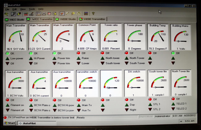
The old version of the software, that is. I like the graphical interface, just one glance is all that is needed:
Burk auto pilot
I have not had a chance to fool around with the newer version, the screen shots on the Burk website look a little bit different.
The setup and programming of macros is pretty easy; power/pattern change times, Pre-sunrise, and post-sunset functions, automatic tower light monitoring, AM Directional Antenna readings, and automatic transmitter restoration routines. If programmed correctly, the software can eliminate many of those late-night/early-morning phone calls, which is always a good goal.
I sometimes get the distinct impression that the corner office doesn’t understand what it takes to keep a radio station on the air and in good repair. It is most often the problems or “issues” that tend to get the most attention. The things that are working well tend to get ignored. After all, how often do you hear a news report about the airliner that landed safely?
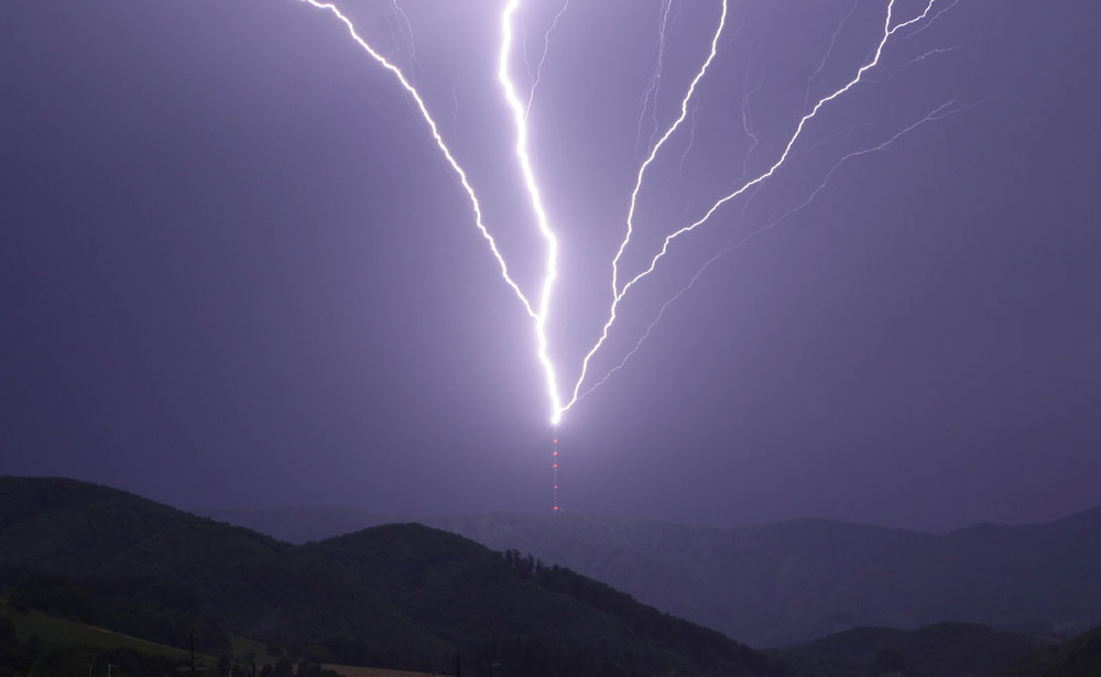
Lightning strike, TV tower
When lightning strikes the tower and knocks the transmitter off the air causing major damage and expensive repairs, that is a problem. When lightning strikes the tower and nothing happens, no problem. What is the difference between those two situations?
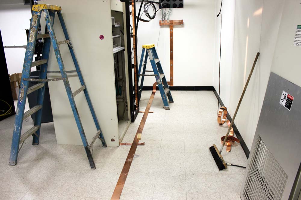
Grounding strap, FM transmitter site
If the generator starts and runs during every power outage and has done so for the last five years straight, it is obviously a reliable unit, does it need all that maintenance?
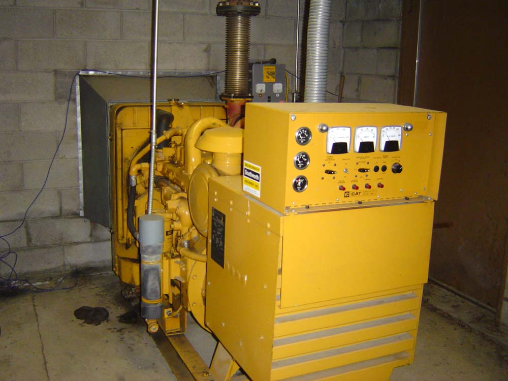
Caterpillar 75 KW diesel GENSET
Money spent on preventing undesirable outcomes can be difficult to quantify as disasters and events that do not happen are ill defined. It is difficult to quantify the “amount saved” on something that didn’t or won’t occur. Using past situations is good start, but that only covers a fraction of possible outcomes. In order to invest money wisely, one has to look at the probabilities. If there is an unlimited budget, then the probability exercise should be minimal, however, there is very seldom an unlimited budget.
For example, how much does a back up STL system cost vs the risk of being off the air while the main STL system is being repaired? How often do failures occur, when are they likely to occur and for how long are all good questions. Is there an alternative to a full backup like an IP CODEC? Such a solution would cover all aspects of the STL system including antennas, transmission line, transmitters and receivers.
There are certain FM stations north of here that have neither RADOMES or antenna heaters. Once every two years or so, the antenna ices up and the transmitter folds back due to VSWR. How much of an impact to listeners notice when this happens? If it happened more often, say two to three times a year, would it be wise to invest in some type of deicing equipment?
What is the ownership and management opinion on off air conditions? I have often heard tell “Oh, its only the AM, we don’t mind if it goes off the air.” That is, until it actually goes off the air, then it is a big problem.
Based on my and others experiences, these are the things that will happen at an average transmitter site:
The electricity will go off at least once per year for several hours.
The main transmitter will fail at least once every two years.
Lightning will strike the tower at least once per year.
The STL system will fail, at unknown intervals.
At studio sites, these things will occur:
The file server will crash depending on the operating system
The telephone lines and or T-1 service, internet service, ISDN etc will go out
The electric power will go out for several hours
The satellite dish will fail once every two to three years
If there is a tower, it will get struck by lightning
Other site specific things can occur like floods, blizzards, earthquakes, fire, etc.
Money spent on backup systems for those items is good insurance. Not only will the station stay on the air, the on call engineer’s phone will ring less often, which, if you are the on call engineer, should make you happy.
If a full backup is not available, a second transmitter for example, having a good stock of spare parts on hand can mean the difference between an early evening and an all nighter. Keeping good maintenance logs and well documented repair records can point out trends and give a good basis for ordering spare parts.
Repair trends are important. If the same part seems to be going bad over and over, it is time to dig deeper and find the cause of failure.
The old adage “An ounce of prevention is worth a pound of cure,” still holds true.
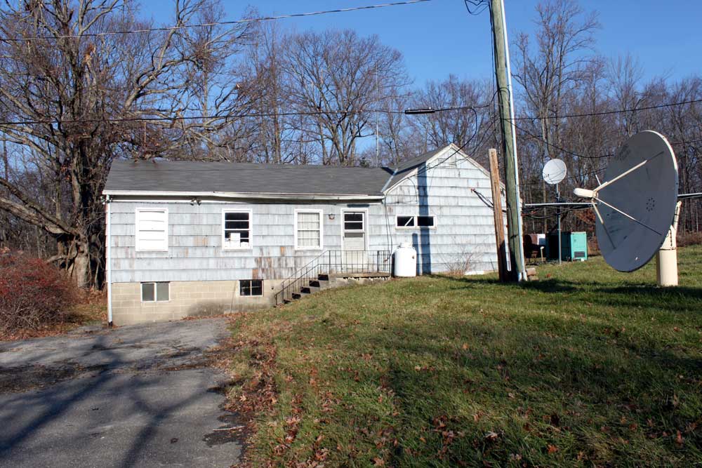
Blogging has been light due to workload being heavy, at the moment. We are engaged in moving transmitters out of this old house:
WINE 940 WRKI 95.1 former studio and transmitter site
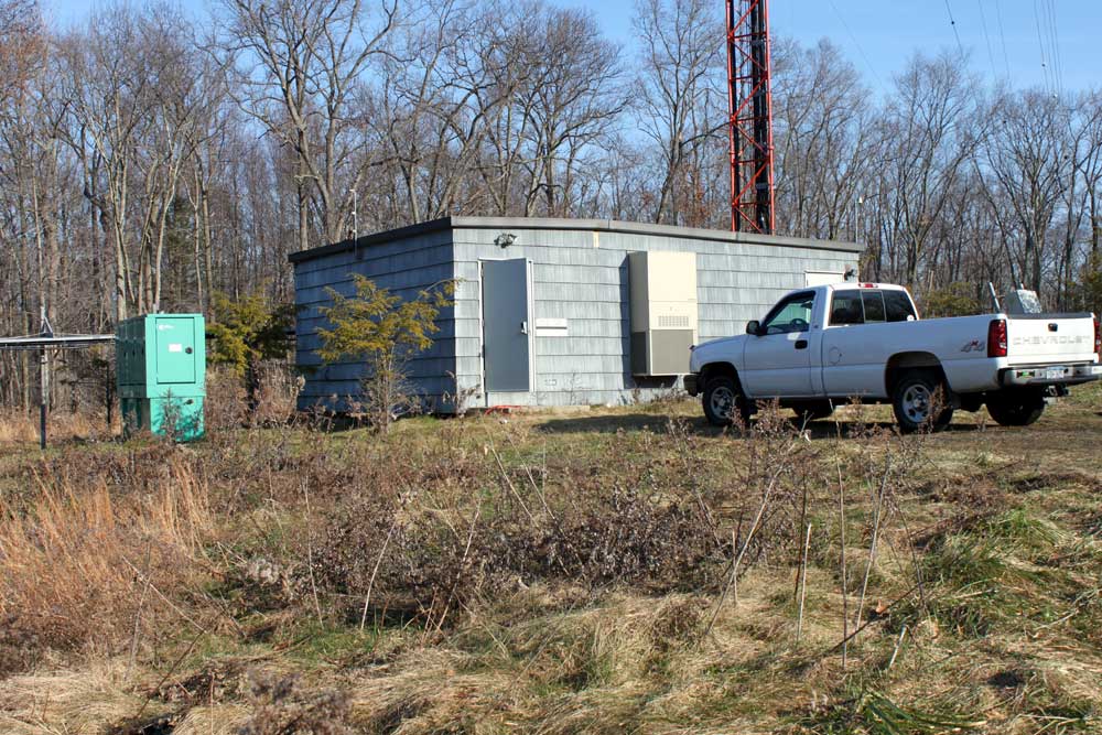
Into this new transmitter building:
WINE WRKI transmitter building at base of tower
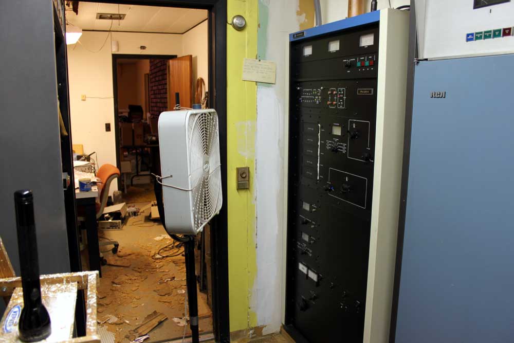
The former building was the original studio for WRKI, 95.1 MHz, which signed on in 1957. The co-located AM station, WINE 940 KHz, did not sign on until 1963. As such, the building is a little worn around the edges, so to speak. The FM transmitter has an auxiliary cooling device, for those hot summer days as the building itself is un-airconditioned:
WRKI Harris FM25K transmitter, circa 1986
The rest of the building is in similar condition. Ceiling tiles are falling off the ceiling and getting ground into the floor, junk is piled up in almost every corner, rodent feces, and the basement, don’t even get me started on the basement.
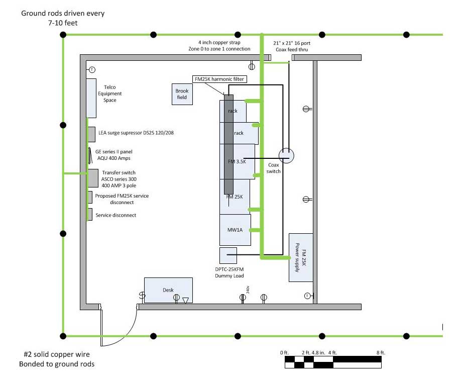
The basic floor plan for the new building is simple:
WRKI WINE transmitter room floor plan
Right now, the preliminaries are being done, mounting the coax switch, running conduit, pulling wires, etc.
A few design notes:
This building is much closer to the tower, which is sited on a high hill (715 feet, 218 Meters) and sticks up 500 feet (152.1 Meters) above that. Basically it is the area lightning rod, thus special attention will need to be paid to grounding and bonding. I decided to isolate the electrical ground in favor of the RF ground for lightning protection. This involves putting toroids on the electrical ground conductors.
The building itself is shielded with continuous steel plating, but that has been cut in a few areas to install air conditioners. Those areas will have to be repaired and the AC units bonded to the steel plate.
Back up cooling will be in the form of a large exhaust fan and intake louver.
The tower itself is AM radiator for WINE. It is 170 degrees tall, which means high RF fields at the base, therefore good RF bypassing is needed.
The transmitter room itself is fairly small for what needs to go in there. careful design and placement is required.
Here are some in-progress pictures:
WRKI backup transmitter, Harris FM3.5K, coax switch in the background
The first order of business was retuning a Harris FM3.5K transmitter to function as the backup. The current backup transmitter is an RCA FM20E, which no longer runs. After the move is completed, that transmitter will likely be scrapped.
I attached super strut to the ceiling at four foot intervals. I used this strut to support the 4 port coax switch. All coax in the transmitter room is 3 1/8 inch hardline, which has a power rating of 40 KW. Since the transmitter power output is 20 KW, this leaves a lot of head room for problems. When working with a 3 1/8 inch coax, it is important to remember to cut the inner conductor 1 1/2 to 1 3/4 inches sorter than the outer conductor, otherwise the stuff doesn’t go together right.
The 30 KW air cooled dummy load was moved up from the other building and connected to the coax switch. This allowed the backup transmitter to be tested.
WRKI backup transmitter and dummy load
Three inch ground strap connects all the transmitters, racks, and dummy load to the station ground.
WRKI ground strap, new transmitter building
Electrical requirements are being met by a 400 Amp service backed up by a 120 KW generator. Once the conduit work is finished and all the wires pulled, the coax to the old building can be cut and brought into the new building, then the station can go on the air with the “new” backup transmitter.
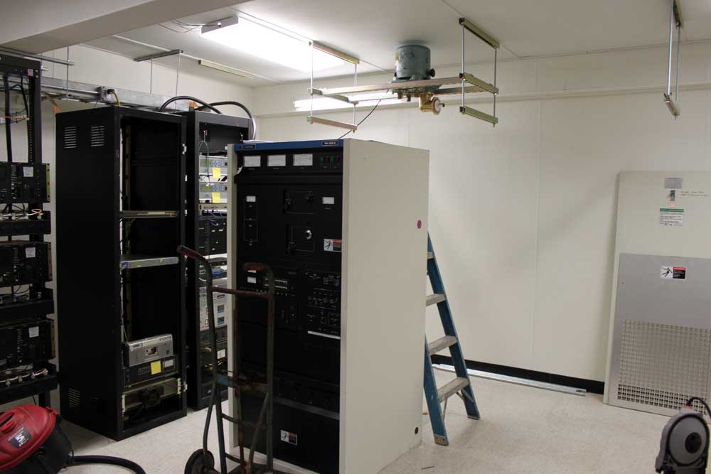
This is the main transmitter for WYJB in Albany, NY. The backup is the Harris FM20H3 on the right. I haven’t turned that unit on lately, but it normally makes quite a fuss the first time the Plate On button is pushed. The FM 20T on the other hand, is mellow and even-tempered.
WYJB 95.5 Mhz, class B, transmitter Albany, NY
One other thing of note; The FM20T is still on its original tube. I looked up the maintenance records for this transmitter, it was installed in December of 2000. Eleven years later, the 4CX15000A (ed note; 4CX12000A) is still cranking out 15 KW TPO, which is impressive. I found that high-power ceramic vacuum tubes actually seem to last longer when run closer to their limits than those that are running at half power.
After the tube is in the transmitter, run it at a full filament voltage for at least an hour or so before turning on the plate voltage. This allows the getter to absorb any stray gases in the tube.
Once the plate voltage is applied, proper tuning should be completed as quickly as possible. Tuning procedures vary from transmitter to transmitter, however, the general idea is to obtain the maximum power output for the least amount of plate current while keeping the PA bandwidth within acceptable limits. Some transmitters can get narrow-banded at high efficiencies, which manifests itself as higher AM noise.
After the tube has been in use for 90-100 hours, the filament voltage should be reduced gradually until a drop in the transmitter output power is noticed, then increased by 0.1 volts.
This maximizes the filament life for that particular transmitter and power output. Once the filament can no longer boil off enough electrons, the tube power output drops and it is time to replace it.
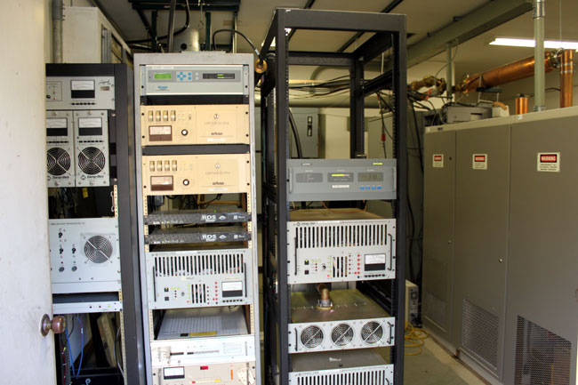
This site also has two other radio stations, WZMR, 104.9 and WAJZ 96.3 , both class A using solid-state transmitters of less than 1,000 watts:
WAJZ and WZMR Energy Onix solid-state transmitters
Not the prettiest sight in the world, but it does stay on the air. There is no money to go back and neaten up this work, unfortunately.
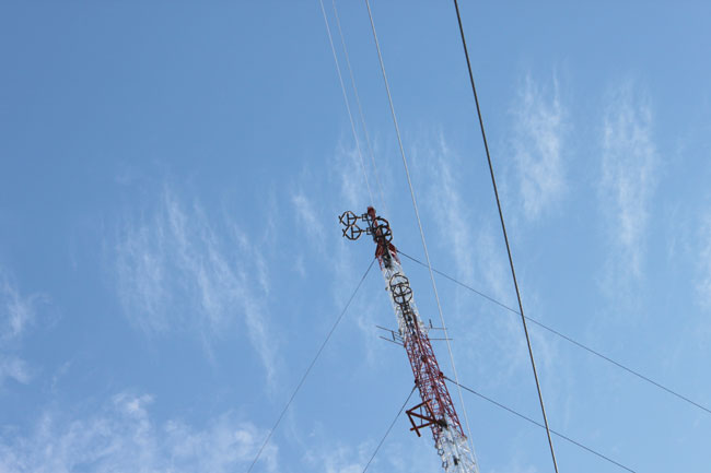
The tower supports all three antennas. There was some discussion of a common antenna for all three stations, however, WZMR is a directional station, thus it would require its own antenna. Doing a common antenna for the other two stations was cost prohibitive, so the tower supports three two bay antennas.
WYJB, WZMR, WAJZ FM antennas, New Scotland, NY
The stations are all located in the New Scotland, NY tower farm. WYJB is licensed to Albany, WZMR is licensed to Altamont and WAJZ is licensed to Voorheesville.