The burned contactor fingers

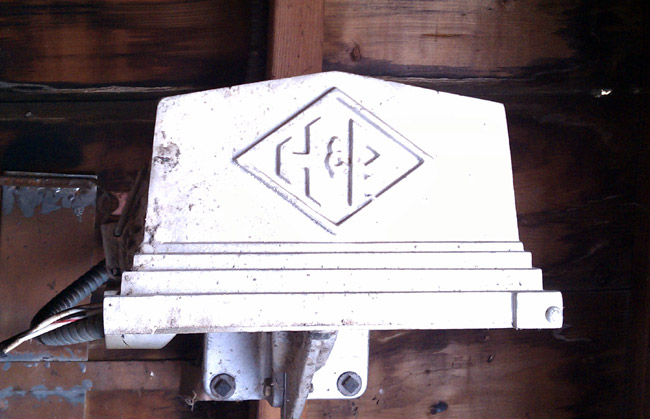
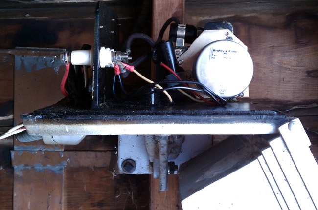
This is a set of burned contactor fingers on a Harris HS-4P 30 amp RF contactor:

Harris HS-4P RF contactor
Harris HS-4P RF contactor with burned finger stock

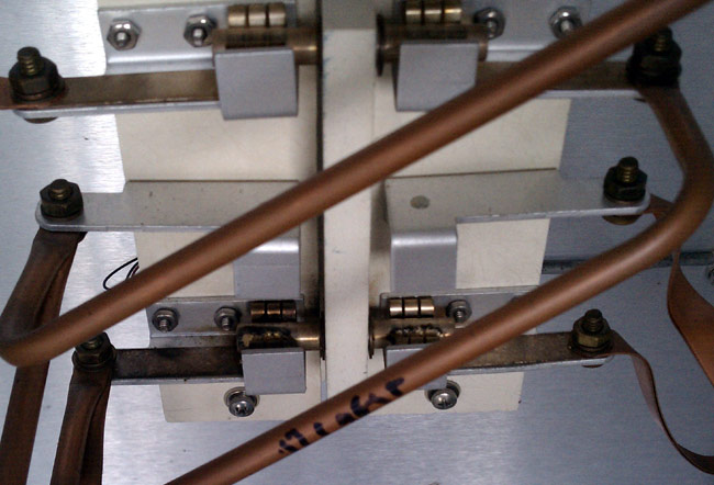
The back story is this:

The contactor in question is at the base of Tower #3 of the WBNR (1260 KHz, Beacon, NY) antenna array.  This is the tallest of all the towers, at 405 feet.  As such, it gets struck by lightning often.  There was at least one occasion where one of the inductors in the ATU got “sucked in” due to the huge magnetic field of a high current strike.  It is not at all surprising to me to find other component issues in this ATU.  Because of the burned contacts, I’d suspect that the station was switching modes under power, but I didn’t see that happening today.

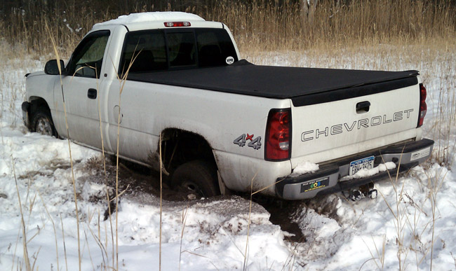
The problem manifested itself in very high SWR after changing over from day pattern to night pattern.  This did not occur every time, in fact, it only occurred once in a great while at first.  Then, over the last couple of months, it began occurring more and more often.  Since the snow drifts are now down to a manageable six to eight inches, it was a good day to go out and do some exploring.

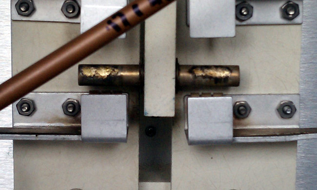
First of all, I put the station into nighttime mode just to confirm that there is still an issue.  The transmitter, a Broadcast Electronics AM1A showed very high SWR and carrier fold back.  Left it in night pattern, but turned it off and took a walk, not a drive, to Tower #4 which is all the way at the bottom of a hill, near the old City of Beacon landfill.  I figured that I would check that one first, then look at Tower #3 on the way back.  When I got to Tower #3, I found the issue right away.

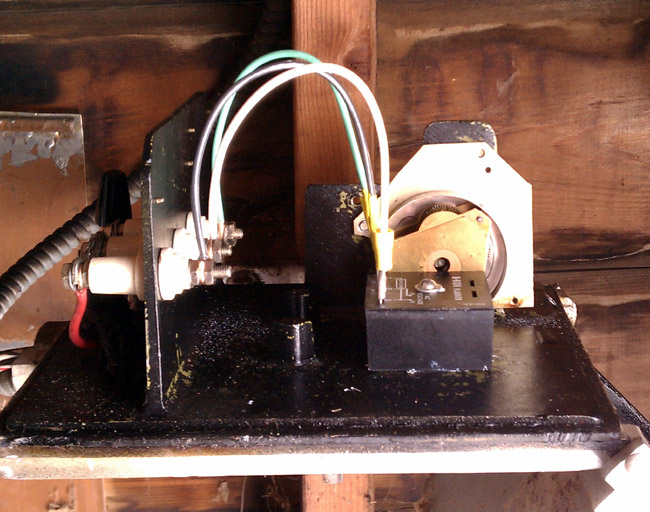
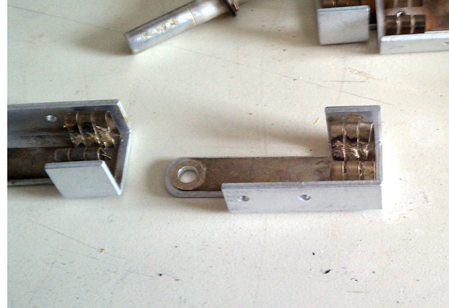
Fortunately, I was able to salvage a set of contact and contactor bar from another relay in the same ATU that was not using them.

Burned RF contactor bar

The night pattern is only 400 watts, but these are tall towers, 225 degrees, therefore current and voltage are high at the base.  In fact, the slightest change at the base of the nighttime towers will greatly upset things.

Burned RF contactor fingers
Harris HS-4P contactor repaired

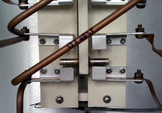
This is the repaired contactor.  I will say, the EF Johnson RF contactors are easier to work on.  Those are the ones with the big rocker bar across the top and two solenoids on either side.  All of the wiring, status switches and contacts are exposed and easy to get to.  This one, not so much.  This is the BE AM1A transmitter

Broadcast Electronics AM1A transmitter

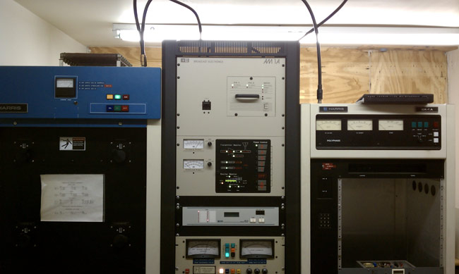
It is not a bad unit, compact, sounds good, is reliable, etc.  In order to work on the power supply or anything in that top cabinet, the whole thing needs to be removed from the rack and taken down.  I suppose that is my only gripe about the thing.

Milwaukee’s oldest radio station

WISN 1130 AM has been on the air since 1922, although not always with those call letters.  In an interesting twist, the license was granted to the local newspaper, the Wisconsin News, and the Milwaukee School of Engineering.  Initially, both entities were programming the station, however, by about 1925, the newspaper was responsible for programming and the engineering school was responsible for technical operations.

In 1941, the station increased power from 1,000 watts to 5,000 watts and added nighttime service.  This is a series of pictures from that time period.

WISN night time allocation study

Back in 1941, nighttime interference was taken seriously.  The nighttime allocation study (on 1150 KHz, WISN’s former frequency) includes co-channel stations in the US, Canada, Cuba, and Mexico.

WISN night time allocation ma

The array consisted of four Blaw-Knox self-supporting towers in a rectangle.  Notice the lack of fencing, warning signs, and the like around the towers.

WISN antenna array
WISN antenna array

From the front of the transmitter building

WISN transmitter site, 1941

The site looks well designed, no doubt manned during operation, which at the time would likely be 6 am to midnight except under special circumstances.   Most of these old transmitter sites had full kitchens, bathrooms, and occasionally a bunk room.  The transmitter operators where required to have 1st telephone licenses from the FCC.   There is only one manned transmitter site in the US that I know about; Mount Mansfield, VT.  There, WCAX, WPTZ, WETK, and VPR have their transmitters.

WISN RCA BT-5E transmitter, 1941

The WISN RCA BT5E transmitter looks huge for that power level.  Back in the day when AM was king, these units were designed to stay on the air, no matter what.  I don’t know too much about this model transmitter, but if it is like other RCA/GE models from the same era, it has redundant everything.

RCA AM antenna monitor

Old school antenna monitor.  I have never seen one of these in operation, however, as I understand it, the scope was used to compare the phase relationship of each tower against the reference tower.

These pictures are of the WISN 1150 array was it was in 1941.  Since then, the station has changed frequencies to 1130 KHz and increased power to 50,000 watts daytime/10,000 watts night time.  The daytime array consists of six towers and the night time array has nine towers, all of which are 90 degrees.

Special thanks to John A. for sending these pictures along.

The mechanical tower light flasher

This is a Hughey Phillips mechanical tower light flasher that has been in service since 1960. Basically, it is a motor connected to a cam that rocks a mercury relay back and forth. These were standard technology for tower lights from the 1930s through about 1970 or a little later.  They were very reliable, we still have some with a “pancake motor” in use on some of our towers.  They were very robust and immune to lightning damage, RF interference, and other problems.  The only maintenance that I can think of is lubricating the motor bearings.  Eventually, however, they do wear out.  Cold weather seems to take its toll, often causing the motor to stop.

Hughey and Phillips mechanical tower light flasher

This particular unit is mounted inside the tuning house for the far tower (north tower) at the WGHQ antenna array.  It has finally reached the end of it’s existence; the motor bearings are shot and it has gotten stuck in both the on and off position this year causing the FAA to be notified of the malfunction.

WGHQ 920 Khz Kingston, NY antenna array

Today, I am replacing it with a solid-state flasher (SSAC B-KON FS155-30RF).  Solid-state flasher units have been known to malfunction in high RF fields, such as AM towers.  To cure that, the manufacturer has built-in 0.01 uf bypass capacitors, hence the “RF” suffix.  Older units did not have built-in bypass caps, so external 0.1 uf bypass capacitors were normally installed on units mounted to AM towers.  While I was working on this, I turned the transmitter down to 500 watts, no need to get any RF burns.

Naturally, this has to happen after there is two feet of snow on the ground.  Also, it should be noted that this is the furthest tower away from the transmitter building.  Now where did I put those snow shoes?  Never mind, it has been very cold and the ground is frozen solid, I’ll take the truck…  This is good because I will have all the tools, drills, nuts, and bolts without having to walk back and forth several times in the snow.

Hughey Phillips mechanical beacon flasher

I removed the motor and mercury-filled relay.  I’ll have to figure out how to dispose of the relay.  I then drilled a mounting hole through the base of the old flasher housing and bolted the solid-state relay to it.  This is required because the solid-state relay needs a pretty good heat sink.

SSAC B-KON tower light flasher

Turn everything back on and:  Ta-da! All works normally, the tower beacon is flashing away up there.  Time to leave.

Truck stuck in swamp

Pull forward about 2 feet to turn around and CRUNCH!  The truck goes through the ice of a hidden stream.  Any attempt to move only makes it worse:

Truck rear burried to axle

Put in a phone call to the one guy I know that can get me out.  About an hour later he shows up with chains, a shovel, and a come-a-long.  We attach the come-a-long to the fence support post and pull the truck out backward 1/2 inch at a time.  It took us about an hour and a half to get it all the way out so I could drive it back across the field.  I’d have taken some pictures, but my guy; was a little grumpy.

I won’t do that again.

Still, I did the job I came to do, so it was a good day after all.

WE2XRH and the NVIS antenna

WE2XRH looks like an Amateur radio call sign but it is actually the call sign of an experimental short wave station in Alaska.  Transmitting DRM on 4.85 MHz, 7.505 MHz and 9.295 MHz with a Near Vertical Incident Skywave antenna system, they hope to cover all of Alaska and almost nowhere else with shortwave broadcast.

WE2XRH DART coverage with NVIS antenna system

This license was granted for two years in August of 2008 and renewed again this September until  July 2012.  According to the website Nextgov.com:

The company told FCC that its initial tests would be funded by and conducted for the Defense’s Joint Electromagnetic Technologies program, a classified operation whose mission is to develop technologies for use by special forces and intelligence units.

Defense also will supply surplus transmitters from the closed, Cold War-era Over the Horizon Radar, located in Delta Junction. The radar system bounced shortwave signals off the ionosphere to detect aerial targets, such as Soviet bombers, at ranges up to 1,800 miles.

The transmitters are 100 KW Continental HF units, which for this applications are running about 20 KW.  According to this Yahoo Groups posting, several Japanese shortwave DXers have received the station in late 2009, but nothing recently.  I shot an e-mail off to their information address, but did not receive a reply.

On High Frequency (HF) NVIS has been used for several years where line of sight VHF communications are not possible.  Soldiers during the Vietnam war noticed that if a vertical whip was bent over so that it was horizontal to the ground, the signal strength was slightly less but the signals were much less prone to fading.

Near Vertical Incident Skywave antenna angle vs. distance

In this case, WE2XRH is using a crossed dipole antenna which generates a circularly polarized field.  With traditional HF skywave, polarization is not a factor since the ionosphere usually causes some field rotation anyway.  It is interesting that the system had this design consideration.

The NVIS is a novel approach and it may work on Medium Frequency (MF) during the night time, but daytime coverage would still have to rely on ground wave signal.  The FCC has historically approached MF skywave as a secondary and unreliable transmission method.  The idea being to reduce the antenna take off angle to as low as possible, hence the popularity of taller than 90 degree towers.  There is good validity to that practice as mixing the ground wave and skywave components at a receive antenna will cause multipath fading.

Setting aside a new broadcasting frequency segment, say 1.6 – 1.8 Mhz, a system could be designed to transmit DRM by using groundwave during the day with a traditional 90 degree tower, and NVIS at night with a horizontal dipole antenna.    Then never the two should meet.  The night time NVIS system would have a small ground wave component, out to a couple of miles.  In addition to that, the night time NVIS system can run on an adaptive power system, when propagation conditions are poor, more power can be applied to the antenna input and in better conditions, power reduced in accordance with a remote receive monitor that reports the Bit Error Rate (BER) back to the transmitter controller.

The best NVIS antenna is the 1/2 wave dipole positioned between 0.1 and 0.2 wave lengths above ground. In the 1.6  to 1.8 MHz band, that equates a half wave dipole antenna 260 to 292 feet long mounted between 66 to 90 feet above ground level.

This would have many advantages over the current directional antenna based MF broadcasting system currently deployed.  The current system is based on pushing potential harmful signals away from a station that was licensed to the same frequency (or an adjacent frequency) earlier.  This puts the onus for proper operation on the broadcast license holder.  Most don’t have the know how or resources to insure that a n AM directional is operating properly.  I would estimate at least half of the directional AM antennas in this country are out of tolerance.  With a NVIS based night time antenna system, coverage areas would be assigned much like an FM allotment.

The BBC conducted medium wave DRM tests in 2007 with satisfactory results during the daytime, but poor reception at night time due to co channel interference.  That is why DRM will not work on the current AM broadcast band and if digital radio is to be broadcast on MF, a new frequency band would be needed.