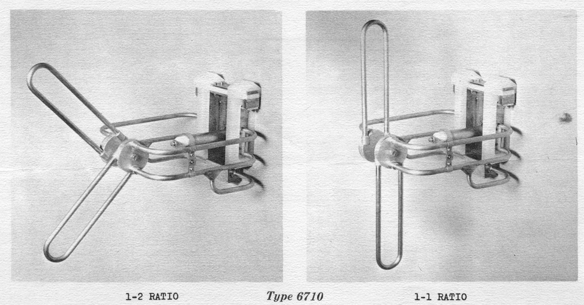
Perhaps that is one Shively Antenna that you haven’t heard of. They were an oddball combination of a horizontally polarized antenna with an adjustable vertical element. This design allowed the station to adjust the ratio of horizontal to vertical power from a range of 1:1 to about 4:1 (H:V). Why would this be a desirable feature?
Back in the early days of FM broadcasting, almost all stations had horizontally polarized antennas. This system worked remarkably well, stations could broadcast at moderate power levels over fairly long, line-of-sight (or mostly line-of-sight) paths. Most FM receivers were stationary units installed in people’s homes often with outdoor antennas.
It was not until the late 1960s and early 1970s that FM radio receivers became a stock option in most low and mid-cost automobiles. It was then that a slight problem with FM broadcasting was discovered; car antennas are vertically polarized. People driving around in their new machines found that the FM reception was not all that great. Stations began adding a vertical component to their signal to help improve the mobile reception situation.
I found this Shively Brochure in a file cabinet drawer at the WFLY transmitter site. This model antenna was ordered and installed by that station in 1970. It had a 3:1 horizontal-to-vertical ratio. Why not install a fully circularly polarized antenna? Because often that necessitated installing a new, more powerful transmitter. Every watt of power taken from the horizontal plane and added to the vertical plane reduced the ERP by that much and had to be made up with more transmitter power output. Oftentimes, the ratio of H:V power would be adjusted to take up whatever headroom there was in the transmitter and the station would run that way until the next transmitter replacement cycle.
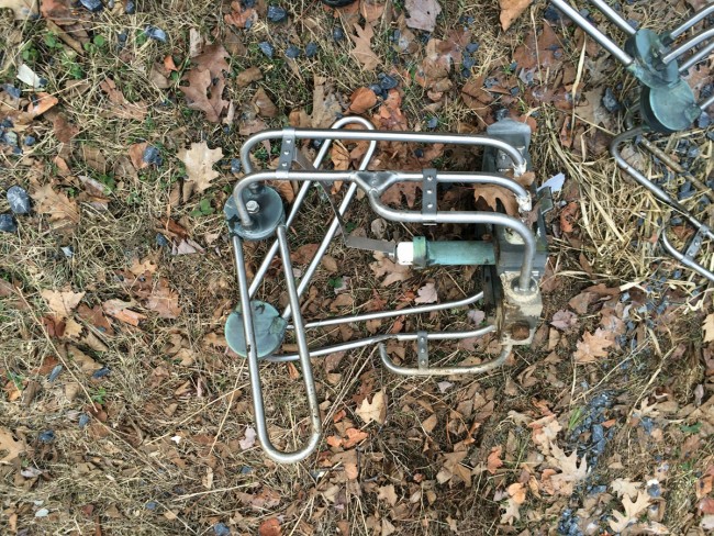
I found the remains of this antenna in the woods, northeast of the tower.
Shively 6710 antenna section
This section looks pretty well destroyed. It is probably better to dispose of these types of things by scraping, them rather than dumping them in the woods. While there is not a lot of scrap value to this unit, it can become attractive nuisance to copper thieves and other vandals if it is left laying about.
It is a strange-looking piece of kit, a sort of make-do until the situation could be fully rectified. I think this antenna was in service until 1986 or 87 when it was replaced with a circularly polarized ERI.
FCC rules stipulate that when a station is operating at variance from its licensed parameters for more than 10 days, Special Temporary Authority (STA) is required. The reasons for requesting an STA are varied but could include things like:
Damaged transmission equipment
Loss of transmitter site or building use
Loss of tower
Eviction
Facilities upgrade or renovation
Natural disaster
The loss of the transmission tower at WUPE-FM falls into one of those broad categories. Thus, we have filed an STA with the FCC for temporary transmission facilities while a new tower is being constructed. Since the old tower is completely lost, we specified a new tower location, new height above average terrain (HAAT), new ERP, and environmental certification. To gather that information, several steps were needed:
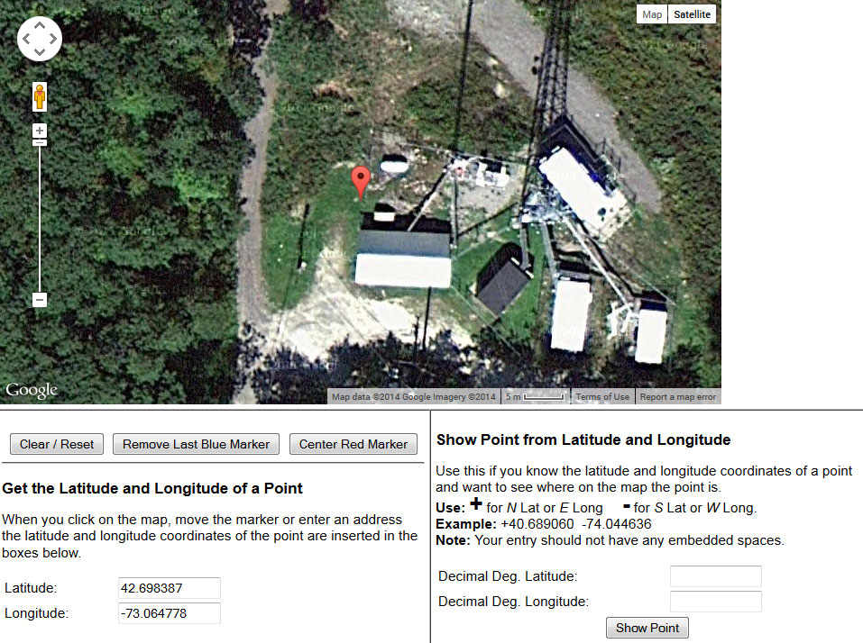
Obtain a new tower location. This was done with a GPS receiver and verified on itouchmap.com. Once the NAD83 position was obtained, it needed to be converted to NAD27 for the FCC filing. The FCC has a conversion tool on its website.
HAAT calculation is fairly simple, use the HAAT calculator tool on the FCC website. For this, the antenna radiation center height Above Mean Sea Level (AMSL) is needed. Using a topographical map, find the ground level AMSL, convert it to meters, then add the radiation center height above ground level (AGL).
The Effective Radiated Power (ERP) calculation is also simple; Transmitter Power Output (TPO) minus system losses (transmission line and antenna gain). It is easiest to do this in dBm, e.g. convert the TPO from Watts to dBm, then add or subtract the gain or losses in dB, and convert the final product back to Watts.
The environmental statement is slightly more tricky. Basically, the filer is certifying that the STA complies with all environmental regulations including OET-65 (RF exposure limits). Since the temporary antenna is significantly lower than the original, some investigation is required. For this, there are two methods to demonstrate compliance; ground measurements with a NARDA meter, or RFR worksheets which are a part of the broadcast station renewal form, FCC-303s.
I have taken the RF worksheet sections out of the 303s and separated them into the FM RF Worksheet and the AM RF Worksheet. These worksheets are not effective for large tower farm-type sites where there are too many variables and RF contributors to be accounted for. The calculations on the worksheets are not conclusive, however, if the facility in question falls under the limits, it is generally accepted as being in compliance. Taking ground measurements with a NARDA meter is the definitive method for determining RFR compliance. Since this is a relatively simple site, the worksheet calculations should be sufficient.
The worksheet calculations show that the RFR is within both the controlled occupation limits and the uncontrolled general population limits.
WUPE-FM temporary antenna RFR worksheet
The position of the new temporary pole was verified on itouchmap.com:
It is never good to be operating at a varience from licensed parameters without notification of the FCC. Such things could lead to fine or other problems for the broadcaster.
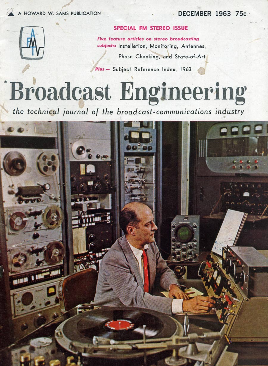
This is a reprint of an article by the same title first published in the December 1963 “Broadcast Engineering” magazine; volume 5, number 12. By George W. Yazell:
In planning a new installation, the broadcast station engineer will be called upon to evaluate the products of various manufacturers before an order is placed for new FM stereo station equipment. In preparing his recommendation, the engineer will review descriptive literature, advertisements, and instruction books. He will seek information and advice from his consultant, other station engineers with stereo experience, and sales representatives of broadcast equipment manufacturers. His thinking may also be influenced by magazine articles and advertisements.
It is unfortunate, but true, that during the engineer’s survey he will encounter many conflicting opinions and claims. Some “advisors” may go so far as to imply that their system of stereo signal generation is the only one worthy of consideration, and all the rest have so many shortcomings as to be impractical or even unworkable.
The simple truth is that any manufacturer offering a transmitter or associated device for sale to broadcast stations must obtain FCC type acceptance. In doing so, complete and authentic test data is submitted for the Commission’s review and approval. Type acceptance by the FCC is your assurance that the equipment will meet certain specifications.
Thus you can either draw straws, or accept the views of the “advisor” with the most forceful opinion and still feel safe that the equipment you recommend will work. A more practical solution would be to prepare a list of equipment and features you require, with careful attention to needs peculiar to your own station; then select the equipment which most nearly matches your requirements.
List What You Have
The first step is to list and evaluate any equipment, facilities, and assets already available for the proposed installation – even if it is only a construction permit, a bank account, and a plan of operations. Some items to consider include:
Ask management for a budget. This is probably the most significant factor in your recommendation. You should set both a practical budget and an absolute top limit. If you find it impossible to do the job within the budget limitations, do not hesitate to say so. Point out that stereo is a two channel system and that in addition to special transmitting equipment, the studio installation will require two of each amplifier, loudspeaker, telephone line, etc. Therefore, a stereo installation will cost considerably more than monophonic facilities.
Review the program plans for the station. The quantity, complexity, and flexibility of the audio equipment selected must adequately meet these needs, with some reserve facilities for future expansion.
You may presently have an FM, AM, or TV station a combination of these. In this case you can probably count on using existing studio facilities, some of the technical equipment, the tower, remote control facilities, and technical manpower.
Consider the abilities of your technical staff. You may be the only engineer, or may have available a large staff of technical personnel. In any event, select equipment having circuits and components your technicians can install and maintain.
Survey the supply situation. Determine the location and stock capabilities of electronic supply houses in your area. Keep in mind that any electronic component must eventually fail; and an inexpensive component can cost hundreds of dollars if you are “off the air” several days while a replacement is being flown in from a distant source of supply. If the supply picture is discouraging, you can best protect yourself by selecting practical equipment employing readily available components – and ordering an adequate supply of spares for parts you cannot obtain locally.
List your needs
Your next step is to prepare as complete a list as possible of the total equipment requirements.
Broadcast Engineering, Typical Stereo Diagram
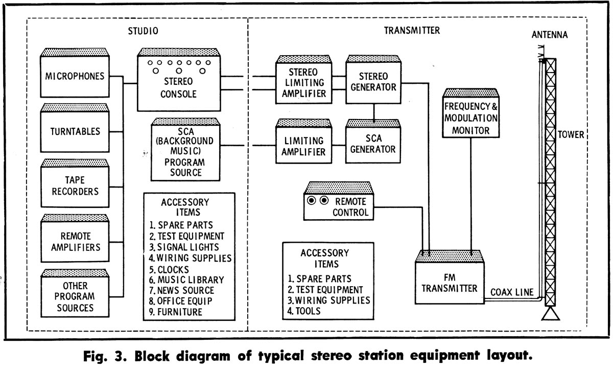
Sketch a block diagram of your proposed layout (Fig. 3). Then prepare a chart of all the equipment you will need with space provided for prices, data, and notes on each device. As you prepare these charts several things will become evident:
You will probably discover more equipment is needed than you originally anticipated.
In determining what must be purchased, you must carefully integrate your needs with the equipment now on hand.
Your ultimate decision will depend on many interacting factors rather than on one outstanding feature of a particular device.
It will be wise to purchase as many items as possible from a single source to take advantage of: the compatibility of equipment that is designed to work together as a system, coordinated shipments and service, possibly lower cost because of quantity purchase, and -if required- simpler finance arrangements.
Making a Decision
After considering the points outlined above, and making the lists, you are ready to select equipment.
If the budget is limited you may investigate the possibility of some used equipment. However, since today’s FCC Stereo Specifications were only established as recently as 1961, there will be little used equipment available. In the majority of cases, converting old monophonic equipment will be difficult, and costly, and the end result may be less than satisfactory. Old “dual channel” audio consoles have been successfully converted, but the process usually requires almost complete rebuilding. It is necessary to install dual faders, correct phase differences, and balance gain between channels.
Used FM transmitters are frequently advertised, but many are left over from the early days of FM. Some transmitter manufacturers of the late ’40s are no longer in business. Replacement tubes and parts are difficult, if not impossible, to get. Some older transmitters lack stability and some contribute to the degradation of stereo separation because they do not maintain the proper phase relationship between upper and lower sidebands. If such a transmitter is to be used, it probably will be necessary to purchase a new exciter and, of course, a stereo generator.
Since stereo listeners are a discriminating and critical audience, audio equipment should be chosen with care. It will be wise to settle for only the finest professional stereo turntable and tape equipment. It is better to have the minimum requirements of excellent equipment than a control room crowded with “make-do” items.
Stereo consoles are available with a wide range of prices and facilities. Some offer stereo channels only for record and tape inputs, while the more complete models even make provision for stereo networks and remote circuits. Much of today’s programming is on records and tapes, but regional “off-the-air relay” stereo networks are springing up. Stereo microphone facilities are a must if you want your locally produced commercials to sound as impressive as your stereophonic music.
Current models of FM transmitters are highly efficient, trouble-free, and easily remote-controlled. All FM transmitters follow one pattern- a basic exciter and a number of amplifier stages to produce the required power output. The power amplifiers in the various models are somewhat similar, except in high-power transmitters (20 kw and up).
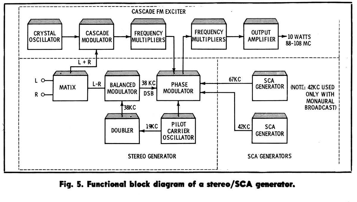
A wide variety of FM exciters and stereo generators is offered, and this is one area in which confusion might occur. (Again, it should be pointed out that all these units are subject to FCC-type acceptance.) A typical exciter and stereo /SCA generating system is shown in Fig. 5. The block diagram explains the signal path and function of the various circuits.
Broadcast Engineering, FM stereo exciter diagram
Conclusion
The selection, installation, and operation of FM multiplex stereo equipment require the careful attention of a highly skilled technician. Installation, adjustment, and maintenance should be in exact accordance with the manufacturer’s instruction book. Following these instructions, the broadcast engineer can feel confident in planning a stereo installation that will be a pleasure to operate and a source of pride and profit.
I found a stack of these old Broadcast Engineering magazines from the early sixties when cleaning out the WUPE-FM (formerly WNMB) transmitter site. I thought it would be interesting to see how Broadcast Engineers some 50+ years ago were planning for FM stereo. One of the stations I worked for, WRVE (formerly WGFM) was the first station in the country to broadcast with the General Electric stereo system. This was later adopted as the standard for FM stereo broadcasting in the US.
As promised in an earlier post, here is an update on the progress at the North Adams tower site for the restoration work on WUPE-FM and WNNI. For those unfamiliar, refer to this post: North Adams Tower Collapse.
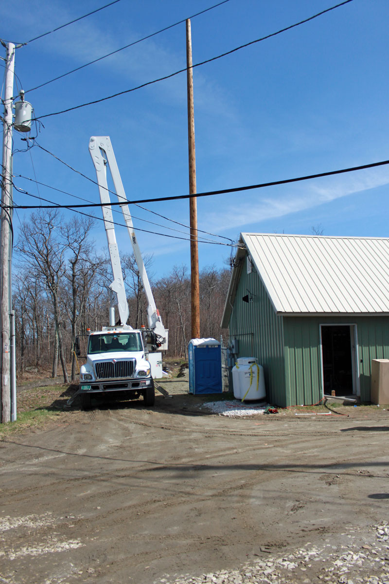
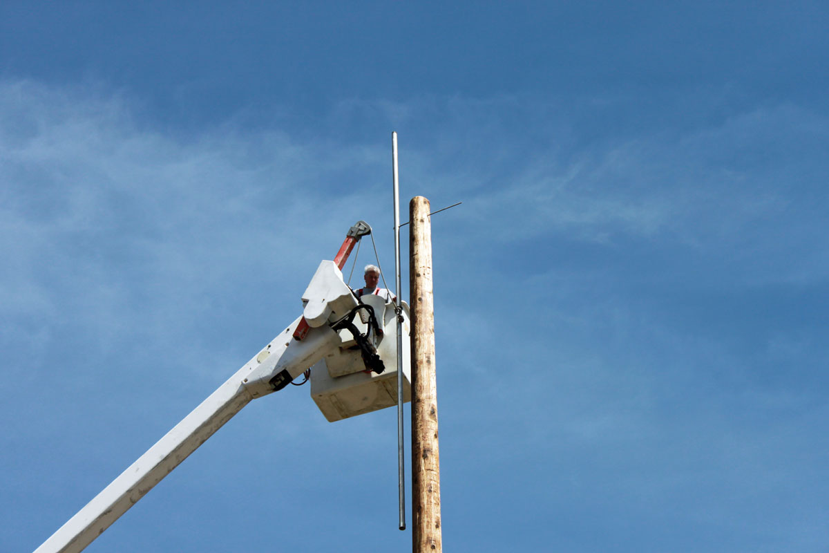
A contractor installed a 70-foot wooden utility pole last week. We ordered new Shively Versa2une FM antennas as replacements for the antennas destroyed when the tower fell last March. These new antennas are field tunable, which is a nice feature. The idea is that this pole will be used until the replacement tower is constructed, which is many months away. After the new tower is up, I would like to keep the pole in place as a backup facility for both stations.
North Adams restoration work
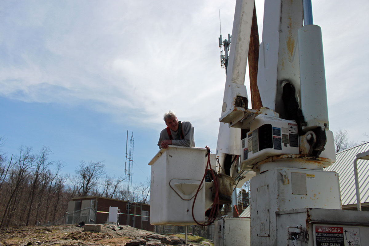
The bucket truck arrived but the driver had a bit of bad news; there is room for only one person in the bucket. The boss pipes up and says “Oh, that’s okay, Paul can go up and run the bucket”
WAT!
Are you sure this is a good idea?
So anyway, it turns out running a bucket truck is not a huge deal; there is a joy stick of sorts that moves the booms around, up down, sideways, etc. Once you get the feel for it, it is pretty easy and three dimensional movement becomes second nature. That being said, at 70 feet in the air, everything gets a little wobbly, so it is best not to jerk the controls around.
The antennas were mounted on a 2 inch pipe which was attached to the pole with 1/2 inch threaded rod. We left a little bit of pipe sticking up above the top of the pole to get the FM antennas as high as possible.
Mounting pole to towerMounting pole to the towerSome dude in a hang glider checking out the work
Getting photobombed by some guy in a hang glider is a new experience. No day is exactly like another in this line of work.
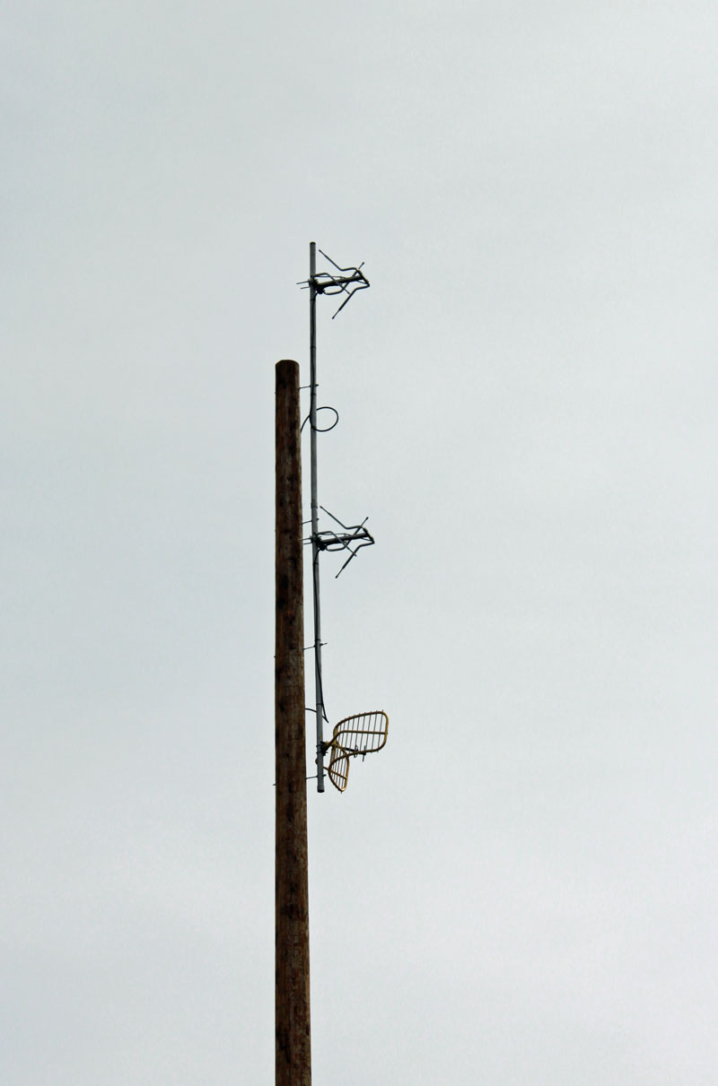
WUPE-FM and WNNI temporary antennas
The antennas were tuned up once they were up on the pole. We did this with the network analyzer, which made the job very easy. WUPE-FM (top antenna) started using this antenna on Wednesday afternoon (5/7) with greatly increased power output. This gets the station almost the same coverage area as they had before the tower collapse. We tested WNNI (bottom antenna) and it all looked good. WNNI is still waiting for a temporary wireless internet feed for program delivery. Once that is established, we will have to do the intermod measurements one more time before they can go on the air.
Here are some pictures of the cleaned-up site:
North Adams, fallen tower removedNorth Adams, fallen tower removed
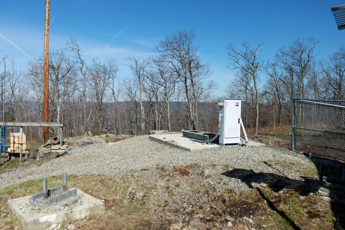
The temporary monopole being used by the cell providers:
North Adams temporary cell tower
Basically the pole is ballasted in place by those huge concrete blocks.