The 4CX250B ceramic tube

4CX250B ceramic vacuum tube

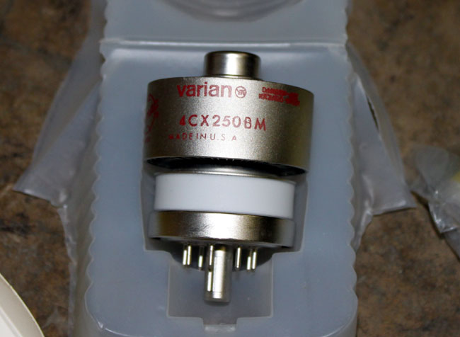
It’s a cute little thing.  These were often used for driver tubes in FM broadcast transmitters.   With the naming conventions of ceramic tubes, we can tell quite a bit about the unit without even looking at the datasheet.

  • The first number indicates the number of grids in the tube, 3 makes it a triode, 4 tetrode, and 5 pentode.
  • The C means it is a ceramic tube
  • The X indicates it is air cooled, a V is vapor cooled, W is water cooled, M is multiphase
  • The 250 is the plate dissipation is watts
  • B is the design revision.

Thus a 4CV100,000 is a vapor-cooled tube capable of dissipating 100,000 watts, something one might find in a high-powered MF or HF transmitter.

Other bits of critical information about tubes would be maximum plate voltage, maximum screen voltage, maximum grid voltage, maximum screen dissipation, maximum grid dissipation, and filament voltage.  Something to keep in mind when tuning a transmitter.

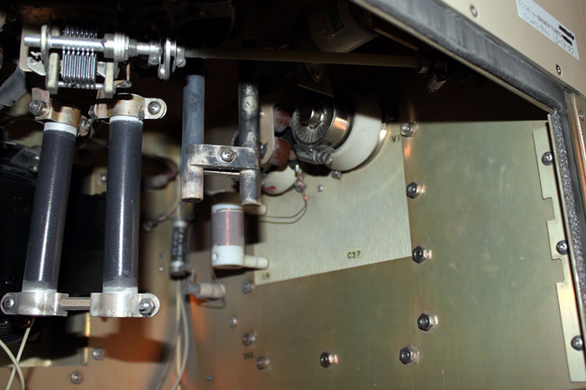
This particular tube is installed in the driver section of a Continental 816R2 transmitter.

Continental 816R2 driver section

I have noticed that these tubes have a much shorter life than there predecessors.  Back ten or twenty years ago, they usually lasted 12-14 months.  The latest set lasted only 8 months and both units failed catastrophically.  That points to one of two things; either something in the transmitter has changed or something in the way the tubes are manufactured has changed.  Once the new tubes were installed, I checked all of the parameters against previous maintenance logs.  I also checked things like air flow, dirt and other possible culprits.

I could find no changes in the transmitter.  The only thing I can think of is the fact that the tubes are installed horizontally, which causes the elements to warp and eventually break or short.

Continental 816R2 transmitter, WFLY, Troy, NY

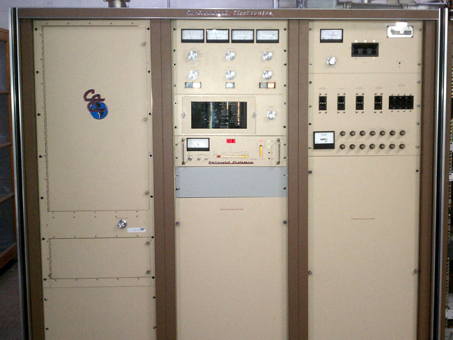
I am thinking we may try to convert the driver section of this transmitter to a solid state unit.  The transmitter itself is 24 years old, but is still works and sounds great.  I’d hate to get rid of it because of its driver section.

The malfunctioning STL antenna

Right after Tropical Storm Irene, it was noted that the STL signal strength at the WHUD transmitter site was low. Normally it was 300+ µV, but now reading around 100 µV, which is a problem. Upon further investigation, it was revealed that the STL transmitter on the intermediate hop had higher than normal reflected power.

Time to call the tower crew.

The STL transmit antenna for WHUD’s STL (WPOU464) hop is a Scala Paraflector (PR-950), mounted at the 280-foot level on this tower:

Scala PR-950 on a guyed tower

The fact that it happened after a major storm and the transmitter was showing higher than normal reflected power indicates a problem with either the antenna or the jumper between the 7/8″ Cablewave coax and the N connector on the antenna.  A measurement with a spectrum analyzer shows very high return loss:

WHUD STL antenna return loss

This shows the distance to fault 413 feet, with a return loss of -7.4 dB.  That distance is either near or at the antenna and -7.4 dB indicates a lot of reflected power.  We had the tower climber take apart the jumper connections and terminate the jumper with a known good 50-ohm load.  The return loss did not change.  We then had him swap out jumpers and reconnect to the antenna.  That did the trick:

WHUD STL antenna with new jumper

Much better, most of the power is now being radiated by the antenna, the VSWR is 1.02:1.  The impedance bump at 51 feet is a sharp bend in the coax where it is attached to an ice bridge.  Reconnecting the transmission line to the transmitter and turning it on confirms that all is normal again.  The problem with the jumper was found in one of the connectors, it was full of water.

Water contaminated Andrew flexwell connector
Water-contaminated Andrew flexwell connector

I cut away the boot, water had entered the connector from the back because waterproofing and tape was not applied all the way to the coax.  This was installed in 1998 when the station moved from Peekskill to its current location in the town of Fishkill.  The fact that it happened now in the nice weather when Mt. Beacon is still accessible and not in the middle of winter means the radio gods are smiling on us.

Donating old equipment

There is a propensity among radio engineers to save old equipment. Sometimes I look at something and think, “Man, that cost a lot of money ten or twenty years ago.”  Truth be told, much of what is saved will never be used again.  This equipment should be scraped or donated to someone who might find it useful.  One thing that is most appreciated by Amateur Radio (AKA Ham) operators is old 1 KW tube type AM transmitters.  Ham operators love these things and with good reason.

A fair amount of repair work, some cleaning, and a bit of reworking will turn what might have been a useless dust collector into a 160 or 80-meter AM rig and with a good story to boot.

Personally, I’d rather see a Gates BC1T or RCA BTA1R off to a new home than off to the scrap yard.  To that end, today we unloaded the BC1T at WLNA to a willing ham.  This particular transmitter had last run in 2001 or so and was used as a spare parts supply for other BC1T transmitters owned by the same company.  There was no way it would ever work again and truth be told, it really wasn’t needed any longer anyway.  Since the Harris MW5B was replaced as the main transmitter by a BE AM6A, the backup transmitter was never used.

Gates BC1T transmitter

John Aegerter, a frequent commenter on this blog, drove all the way from Madison, Wisconsin to pick it up.  Prior to picking up, I removed all of the tubes, transformers, crystals, and glass envelope time delay relays.  I packed up the glass objects in a box.

Gates BC1T tubes, transformers and spares

There were several spare tubes and parts which are no longer needed.  These went with the rig, along with whatever manuals I could find.

Gates BC1T loaded into pickup truck

The transmitter was then loaded into the back of a Dodge Ram 2500 pickup truck and tarped for its trip back to Wisconsin.

Newest Radio Thing

Just in time for the NAB, I’ve been working on this design since my college days. To give you some idea of how long that is, I am nearly 47 years old. I believe it has finally been perfected, now I just need to find somebody to make it. I guess I could send it off to China and get circuit boards made, but they would steal the design.

From the website xkcd.com, which has, perhaps the best website ever published in the history of the internet, here.

Oh yeah, and April Fools!