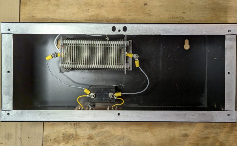
One small RF project that I am working on; a 770 KHz notch filter. I always figure if I am having this problem, then others may be having it too. This is a relatively simple idea, a resonant LC circuit (AKA a tank circuit) tuned to the carrier frequency. It should have a bandwidth of +/- 15 KHz of the design frequency. Another requirement; use the parts I have available. Finally, the environment in which this is to be used is a high-noise room; with lots of computers, LED lights, etc therefore it needs to have excellent RF shielding.
Something like this would work well for anyone that lives around an AM transmitter site and is having problems with receiver sensitivity or transmitter intermodulation.
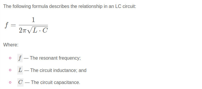
The basic design looks like this:
Parallel LC tank circuit
Time for a trip to the local storage facility known as “The Barn.” In my backyard, there is a small agricultural structure that is used for storage of just about everything. In The Barn, I found several parts salvaged from an old Energy Onyx Pulsar AM transmitter. As such, they are more than capable of receiver operation and could likely handle a fair amount of RF power in the transmit mode.
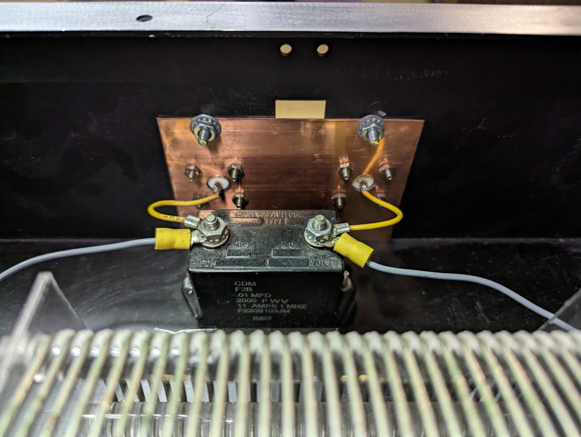
CDM F2B 0.01 uF capacitor with back of N connector inputs
Finding a type F2B 0.01 uF capacitor, rated at 2000 volts and 11 amps, the value of the inductor was calculated. For the inductor, a 20 uH coil with taps will work great. For receive-only applications, much smaller-sized components can be chosen. Also, there are many bandstop filters with multiple poles. Those are great, but I like the simplicity of the parallel resonant LC circuit.
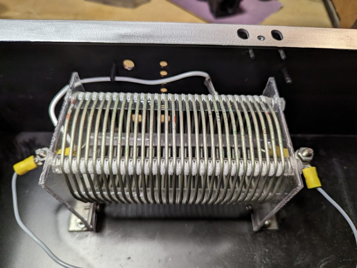
20 uH inductor salvaged from Energy Onyx transmitter
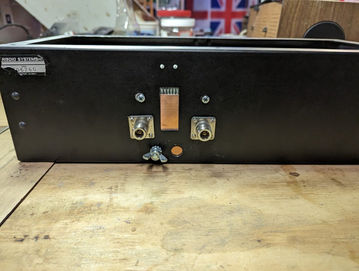
The N connectors were salvaged from I don’t know where and the enclosure used to house a power supply for a Radio Systems console.
N connectors for input and output.
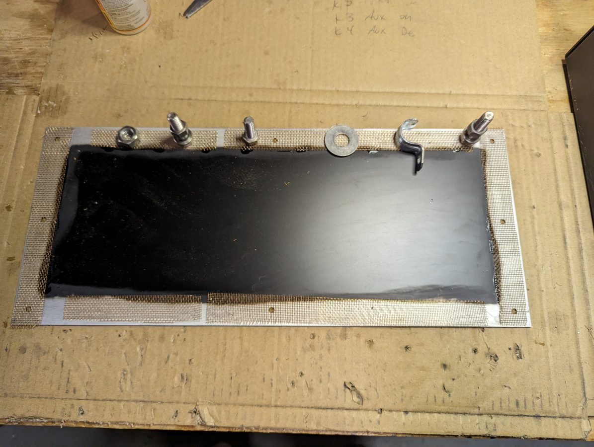
For shielding, I sanded the paint off of the enclosure where the lid is attached and tacked some brass screen down with gorilla glue. This will make a good RF contact surface. The outer of the N connectors are bonded to a piece of copper ground strap which also has a grounding lug on it.
Enclosure lid with brass screen to make contact
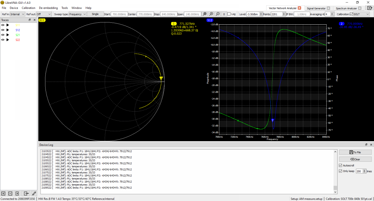
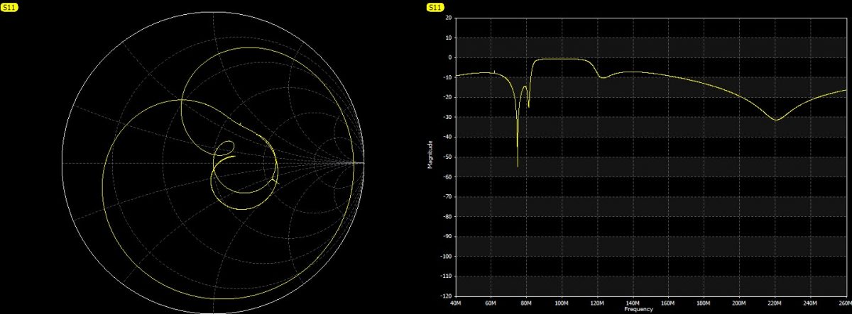
I used the Libra VNA to tune it up:
S12 shows return loss, S21 shows Phase
The scan shows it is -31 dB on the carrier frequency. It is -17 dB on 760 KHz and -20 dB on 780 KHz. This is good, because I may still want to listen to the station on the remote receiver. According to the smith chart, it is actually resonant on 771.5 KHz, but that is close enough for this application. I think the resonance went up slightly when I put the cover on after the tune-up.
There are several tank circuit calculators online. It is best to have more capacitance and less inductance to keep the Q of the circuit low and suppress the sidebands as well as the carrier.
The model for Radio Engineering these days is such that one engineer is covering multiple stations in various locations. At the very least, this person has a full (if not overflowing) plate. Thus, when something breaks, the procedure very often is; to pull the suspected module or board, call the manufacturer and order a replacement. That works as long as the manufacturer supports the model in question or has parts. As we all have learned by now, replacement parts are subject to the global supply chain, which is tenuous.
Then there is the question of AM transmitters. Is it worth it to replace an AM transmitter these days? I suggest it would depend on the market and revenue. In some cases, yes. In other cases, keeping the older equipment running makes more sense.
Troubleshooting is becoming a bit of a lost art. In addition to the time it takes, we tend to be unfocused and obsessed with rapid gratification, ready for the next social media post. What is lacking is the ability to take apart the layers of a problem, accept our initial analysis may be flawed, move beyond those assumptions, and work until the issue is solved. Troubleshooting is often like a crime scene investigation. There are several logical steps;
Assess the current situation; take steps to ensure it is safe to proceed. Remove all power from the transmitter and don’t work on failed transmission equipment during thunderstorms
Gather evidence; look for fault indicators, alarms, automated log entries, burned components, abnormal meter readings, etc
Check external factors; power failures, lightning or storm damage, excessive heat, moisture, etc
Check internal factors; aged components, bad cables or connectors, improperly seated boards or components, and obvious signs of damage
Work from one side of the issue to the other
Check the maintenance logs (if there are any) to see if this problem has occurred before and what was the fix
Use available resources; troubleshooting guides provided in equipment manuals, factory support, and available test equipment
If a failed component is found, make sure that it is the problem and not a symptom of something else
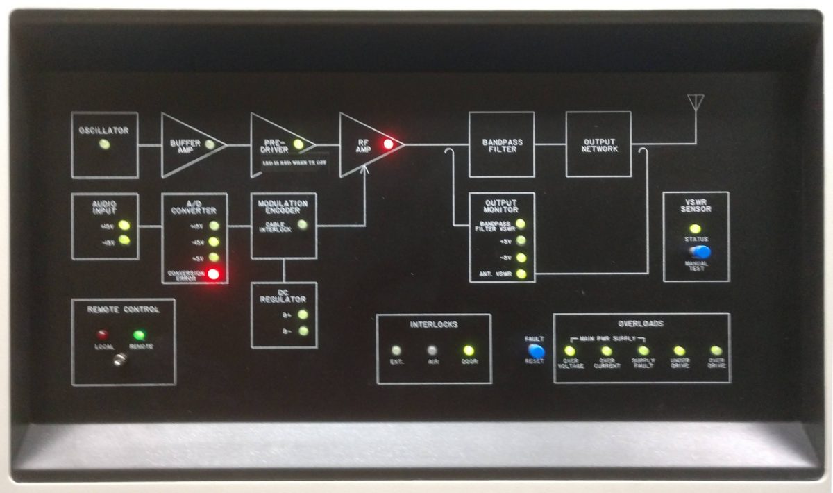
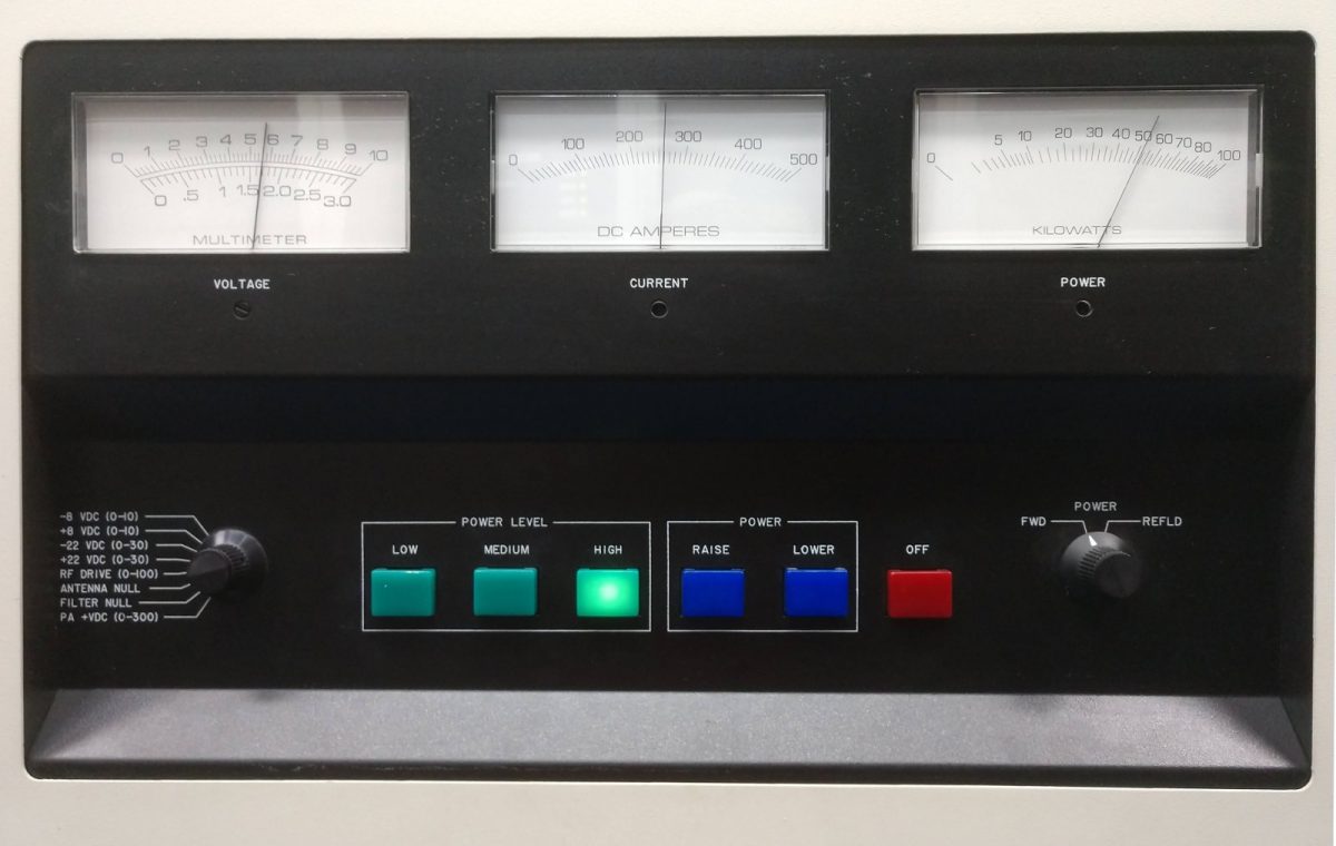
Here is a good example of a recent troubleshooting evolution; I went to change over to transmitter #2 and these fault lights appeared:
DX-50 transmitter, faulted, no power output
The conversion error on the A/D converter indicates why the transmitter power output is zero.
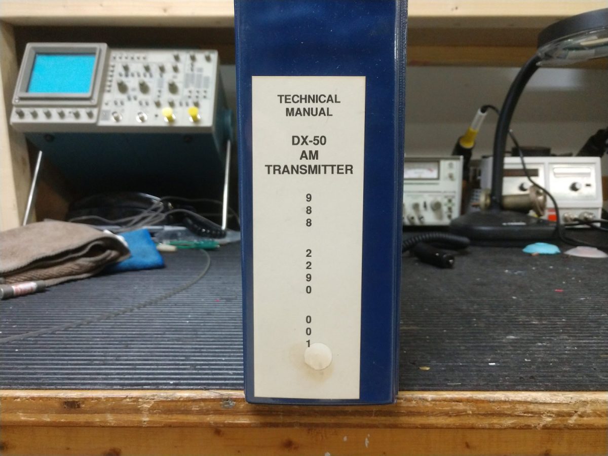
The first step; secure the transmitter, remove all power, etc. Next, consult the book!
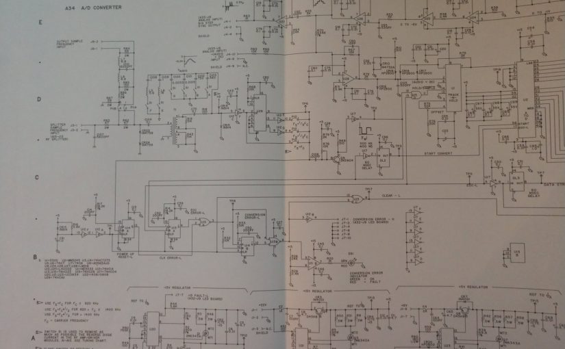
The Harris DX-50 manual gives good troubleshooting guidance. This transmitter was manufactured on March 22, 1990. It has been a reliable unit, to date. Section K.4 Analog to Digital Converter (A34) of the manual suggests loss of audio clock frequency sample due to the following;
Loose connection with the carrier frequency sample cable coming from the RF drive splitter (A15)
Bad or missing jumper connections on P-10, frequency divider section
Bad U-29 (74HC161, 4-bit binary counter, only in use if the carrier frequency is above 820 KHz, Not Applicable)
Bad U-12 (74HC14, Schmitt trigger)
Bad CR13 or 14 (1N914)
Fortunately, there was a working DX-50 about 15 feet away, so I was able to make some measurements at various places on the A/D converter board.
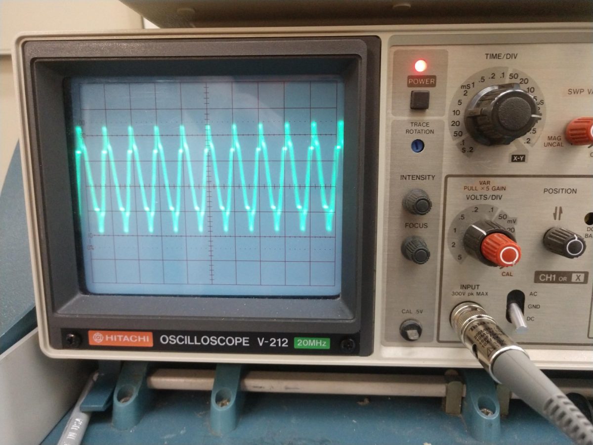
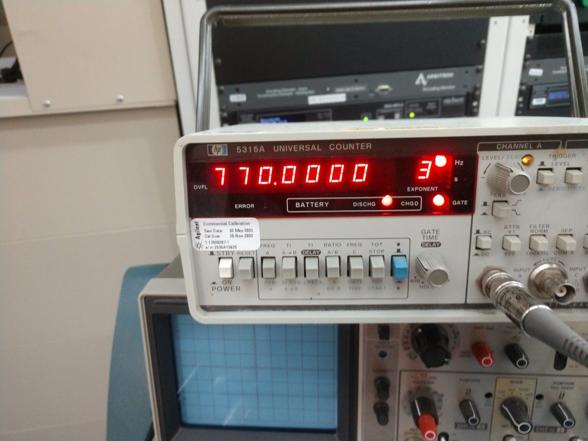
On the working transmitter (DX-50-1), at the RF sample input (input of R83) on the A/D converter board, I see a nice strong sine wave, on frequency:
WABC carrier from RF drive splitter to A/D converter boardWABC carrier frequency
Second, I measured the logic pulses on TP-6, as described in the manual. Those look good.
On the non-working transmitter, I made the same measurements and found a fuzzy sine wave way off frequency on the input of R83. The logic pulses on TP-6 was normal.
Definitely lost the RF sample. Since the transmitter is 32 years old, I suspected the cable (#92, RG-188 coax) between the RF drive splitter and the A/D converter had gone bad. Perhaps rubbed through on a rough metal edge or something like that. Several checks with a Fluke DVM showed that there were no shorts to ground or internal conductor shorts. End-to-end checks on both the shield and inner conductor proved good. So, not the cable…
I then went on a bit of a wild goose chase suspecting the output from the oscillator to be low or the drive regulator power supply was defective. The drive level going into the PA was close to normal but slightly lower than the previous maintenance log entry. Also, drivers 8A and 8B were both on, which is not normal and made me suspect the drive regulator.
I made a call to GatesAir and spoke with a factory rep, who had me swap out the A/D converter, oscillator, driver power supply regulator board, and the buffer amp/pre-driver module between the working and non-working transmitter (while the low-power aux was on the air). With the working transmitter close by, I was able to confirm that these boards or modules were not the cause.
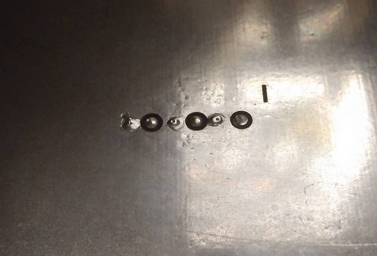
Finally, I went back to the RF drive splitter and use my camera to take a picture:
DX-50 RF drive splitter (A15) J-17, board side
There is a 6-pin connector on the underside of the board (J-17). Pin 2 (from the right) is the center conductor and pin 1 is the shield of the cable going to the A/D converter board. Upon closer examination, the solder joint on pin 2 is suspect. I re-heated this connection with a soldering iron and viola, the transmitter started working again.
WABC DX-50-2, returned to service
The extenuating circumstances; the air conditioning at this site was slowly failing and that part of the transmitter was subjected to heat cycling several times. More recently the HVAC system was in the process of being replaced, of course, on one of the hottest days of the year. This pulled a lot of warm, humid air into the room. Also, as this is transmitter #2, it was not in regular use until recently (we began a procedure for operating on alternating transmitters for two-week periods).
All of this work took place over the course of two and a half days or so. That would be a lot of time for the module swap guys who tend to move on to the next outage quickly. On the other hand, buying a new 50 KW AM transmitter is an expensive proposition these days and there are very long lead times on some of these units. Being persistent and focused paid off in the end.
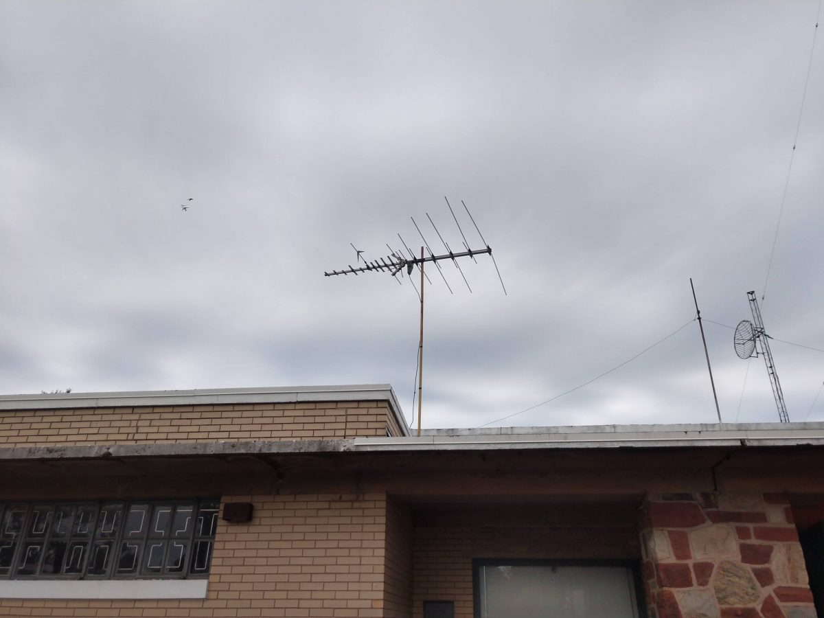
Many people are surprised that OTA TV (Over The Air Television) is still a thing. I am here to say that there are lots of TV stations still broadcasting. OTA is alive and well, especially around big cities. To wit; I noticed this older TV antenna on the roof of a transmitter building in Lodi, NJ. Being curious, I connected an ATSC 1.0 TV to the antenna lead in the kitchen. One scan captured 62 TV channels and sub-channels OTA in the NYC market.
Somewhat aged TV/FM antenna pointed at Manhattan
That site is 10 miles northwest of the Empire State Building.
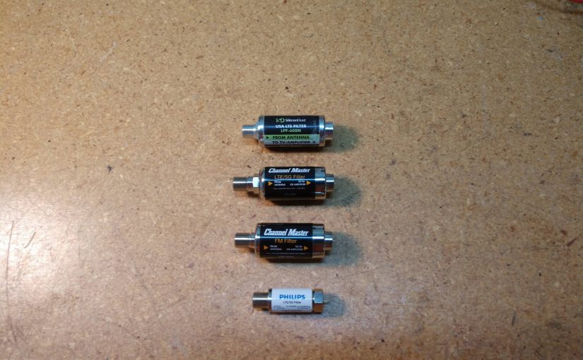
I also noted that the satellite dishes on site have had Terrestrial Interference (TI) filters on the LNBs for many years. Recently, 5G filters were installed as well. Thus, I added a 5G/LTE filter made by Channel Master (part number CM-3201) to the TV antenna splitter. A rescan captured 79 channels. Interesting.
I began ordering TV receiver filters and testing them with my network analyzer. There are many different units made by different manufacturers. The smaller, cheaper units do not have as good performance as the larger, more expensive ones. Go figure.
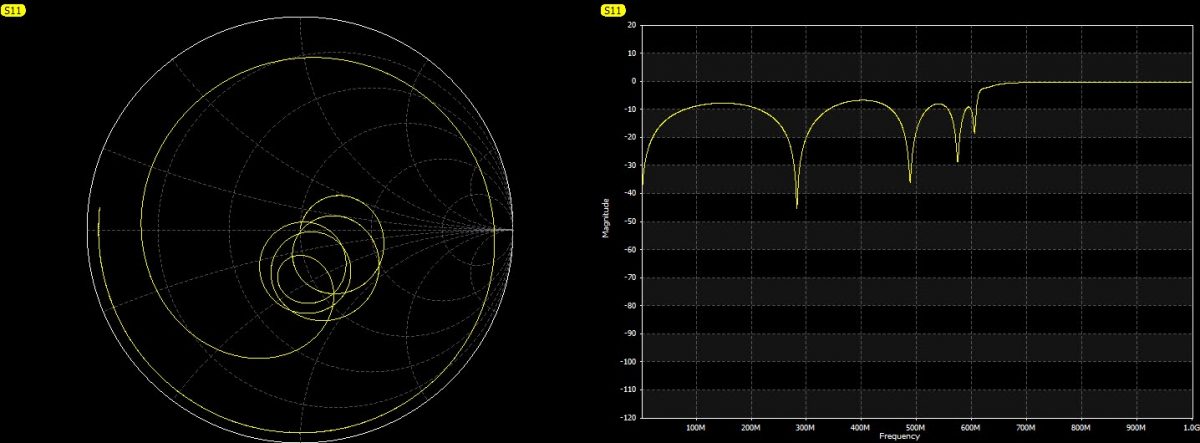
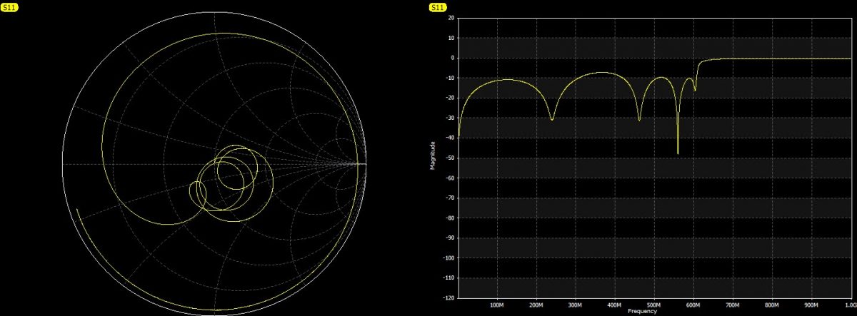
Here are a few sweeps of various filters:
Channel Master CM-3201 5G/LTE filter. Cut off 608 MHzSilicon Dust USA LTE LPF-608M. Cut off 608 MHzPhillips LTE-5G. Cut off 616 MHz
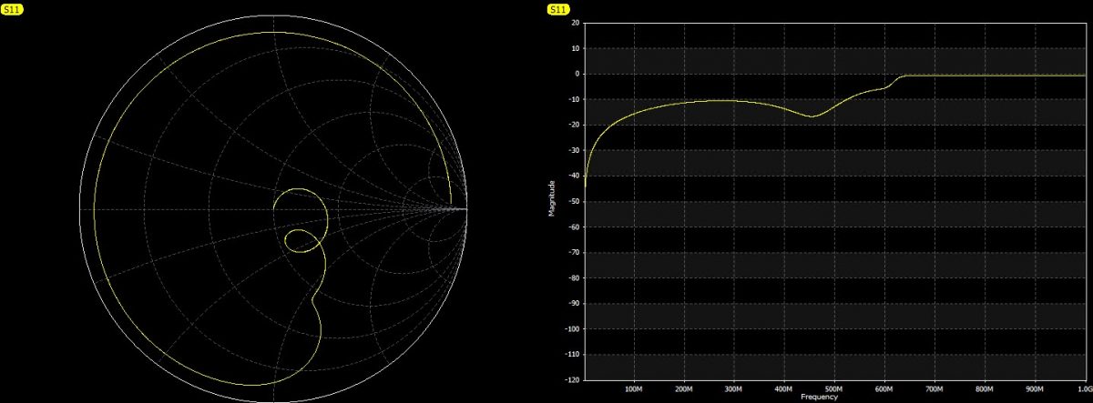
There is also an FM band-stop (Channel Master CM-3202), which is effective for blocking out 87 to 113 MHz.
Channel Master CM-3202 FM band-stop
Sometimes I get questions from non-technical readers, thus for the uninitiated; these sweeps are return loss. The higher the line on the right-hand graph, the less signal will get through the filter. A flat line at 0dB means that little or no signal is getting through on those frequencies.
These filters are helpful, especially with inexpensive consumer-grade TV receivers. If you live near an FM transmitter site, then an FM band-stop filter may help, especially with low and high-band VHF stations. If you live anywhere near a cell site (and most of us do) then a 5G/LTE filter will likely help.
Recently, I pried open my wallet and plunked down the sum of $150.00 for one of these little devices. Now, to be certain, this is not a replacement for a real VNA, especially at a high-power broadcast site. However, it can be used for basic troubleshooting and I have had a good deal of fun fooling around with it.
First, a few quick specifications:
Type: SSA-2N NanoVNA V2.2
Frequency range: 50 KHz to 3 GHz
Power output: -50 to +10 dB
Measurement points: 201 (or 1024 with software and computer)
Measurement types: S11, S12 and S21
Screen Size: 4-inch touch screen
Traces: up to 4
Battery: 3000mAh Lithium Ion
Software OS (VNA-QT): Win 7, Win 10, Linux, MacOS
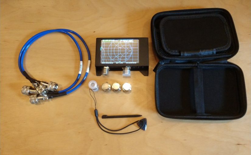
The unit I purchased came with a small carrying case, calibration loads, and test jumpers. The software is downloadable and easily configured.
What I really like about it is the internal battery and the touch screen.
So what can it be used for?
Test a coaxial cable
Measure the length of a coaxial cable
Figure out what frequency an antenna is designed for
Tune a 1/4 wave stub to make a notch filter
Measure the characteristics of a crystal/holder
Measure a capacitor
Measure an inductor
Tune a parallel resonant LC circuit to make a notch filter
Tune a filter can
Test a high pass, low pass or band pass filter
Sweep an antenna (Simple AM, FM, RPU, STL, WiFi)
Check isocouplers for proper circuit functioning
Etc
Pretty much anything you need to know about RF antennas, filters, and transmission lines can be learned with a VNA. One thing to keep in mind; the measurement points are limited, especially in the stand-alone mode. Thus, the smaller the frequency span, the better the measurement resolution will be.
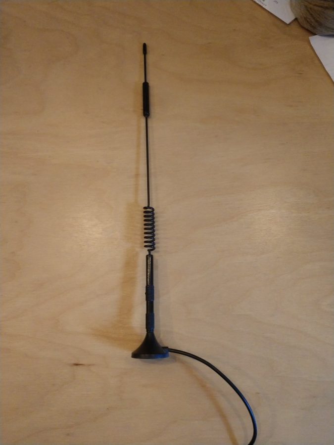
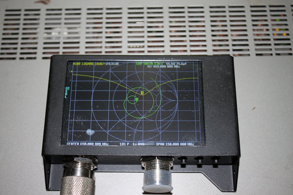
What is this antenna for?Antenna under test, 659 MHz center frequency
While this is a very inexpensive device designed mainly for Amateur Radio, it can be useful to diagnose antenna and transmission line problems. Would I depend on it to make precise measurements? No. Especially things required by the FCC like base impedance measurements on an AM tower or channel filter measurements for a TV station. Would it work at a high RF transmitter site with multiple AM/FM/TV transmitters? No and chances are you might burn out the front end. Those types of things are best done with professional equipment that has much better accuracy and resolution.
It is a pretty good little tool for basic troubleshooting. One can look at the individual components of an AM ATU for example, or measure the input impedance to see if there has been a shift (should normally be 50 ohms). It is small enough that it can be included in a basic tool kit. It is self-powered. Not bad at all for the price.