With the advent of fiber optic cables starting in the 1980s, the majority (one estimate says 99%) of this country’s overseas communications are carried by undersea cables. These are interesting system constructions, being first redundant and second, self-healing. Glass fiber stands themselves are fairly fragile. Bundling several together and then sinking them in the ocean can create mixed results. Deep ocean bottoms are often very rugged, containing mountains, canyons, and fault lines. Thus the submarine cables used have to be pretty rugged.
There is a common misconception that fiber optic cables do not need repeaters. That is not true, while they do not need as many repeaters as copper cable, repeaters are still required approximately every 40-90 miles (70-150 km) depending on the cable type. These active devices are another failure point. Overall, it is a complex system.
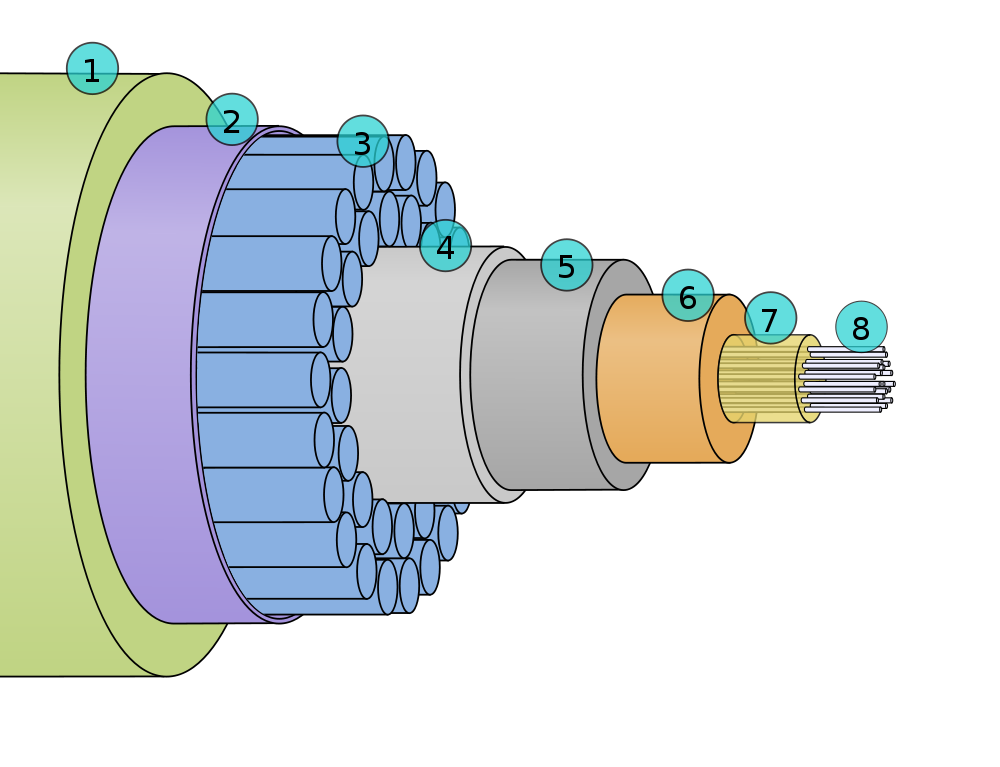
Submarine Fiber Optic Cable cross-section, courtesy of Wikipedia
Cross-section of a submarine fiber optic communications cable:
1. Polyethylene 2. Mylar tape 3. Stranded metal (steel) wires 4. Aluminum water barrier 5. Polycarbonate 6. Copper or aluminum tube 7. Petroleum jelly 8. Optical fibers
It weighs about 7 pounds per foot, which is pretty hefty.
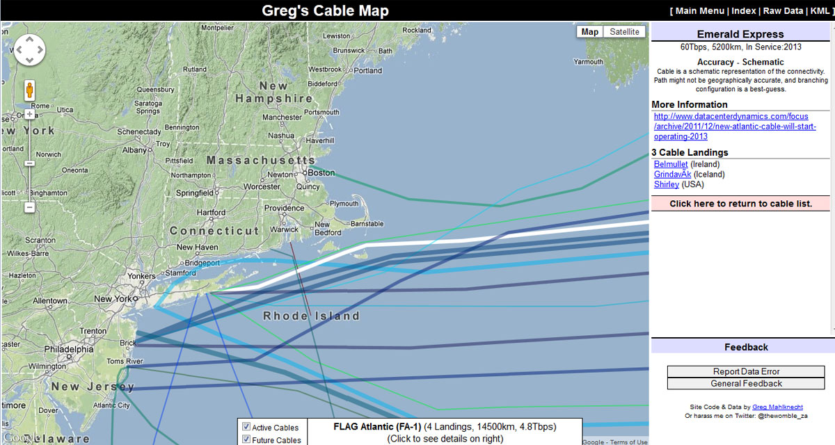
There are a couple of interactive maps online that have detailed information about where these cables go, date in service, and data capacity. My favorite is Greg’s Cable Map which is a Google map with cable data overlayed with a downloadable KML file:
Undersea cable map
This shows a new cable called the “Emerald Express” which is going into service in 2013. Throughput is reported as 60 Tbps, which is moving right along. As noted on the map, this is more of a schematic diagram connecting two shore side points. The path the cable takes is an estimate and the actual geographical location may (is likely to) be different. Click on any line on the map for cable information. Most cables have their own web page and Wikipedia article.
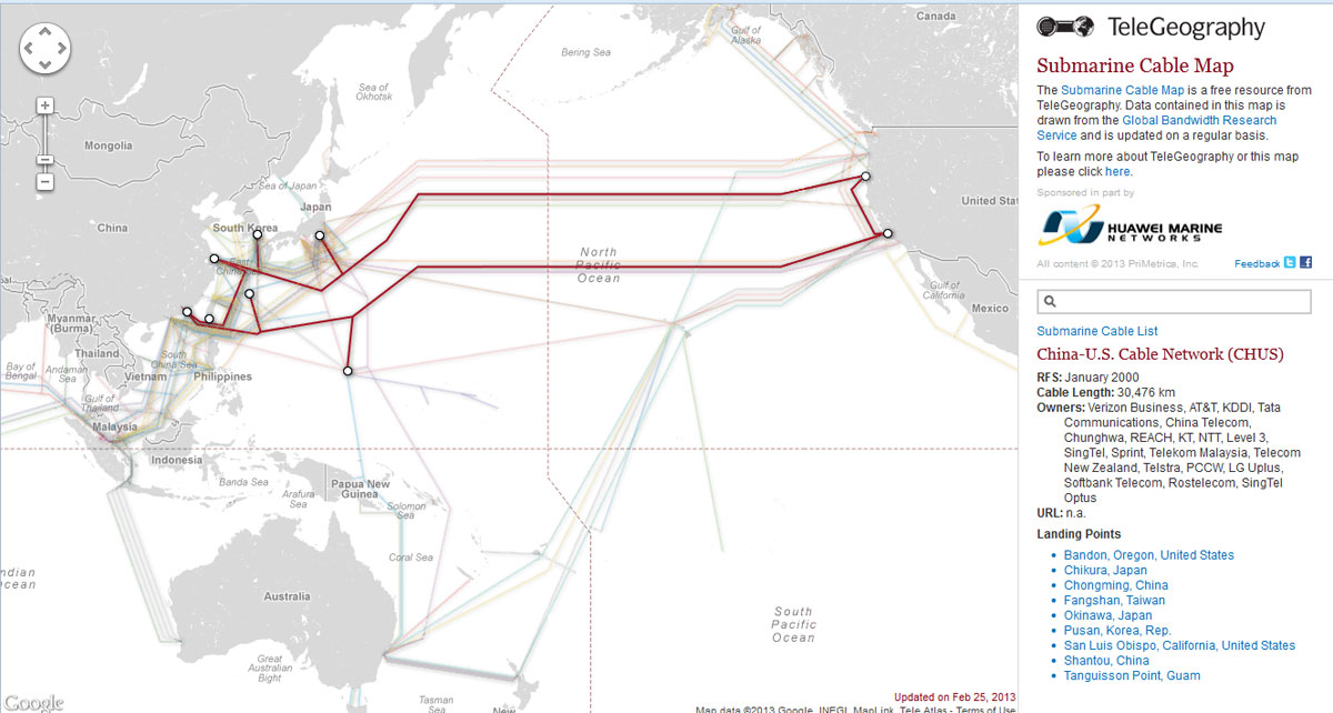
Another undersea cable map is the Telegeography Submarine Cable Map, which has many of the same features noted above:
China US submarine Cable network diagram
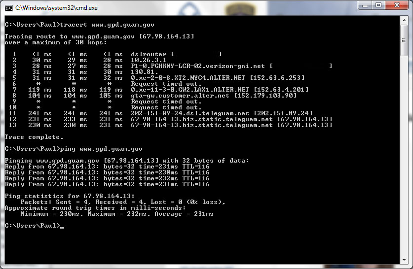
Just in case you were wondering, as I often do, how a TCP/IP connection is being routed to any given place. For fun, I tried a trace route to a known server on Guam and found the results interesting:
Trace Route, Guam
Approximately 231 ms round trip route from NYC to LA to Guam and back, which is over 8,000 miles (12,850 km). A few of the intermediate routers did not answer and I tried this several different times; the same routers time out. This missing information looks to be small steps, not large ones. So, which cable goes directly from LA to Guam? Possibly the China-US Cable Network (CHUS) (picture above). At 2.2 Tbps and landing at San Luis Obispo, that is the likely candidate for the cable that carried my data.
As a general exercise, it is kind of fun, although it may be harder to figure out a particular route to say London or Berlin because there are many more different possibilities.
Route latency is something to keep in mind when planing out AOIP connections for remotes and other interactive type connections between studio and remote location. Almost nothing is worse than that half second delay when trying to take phone calls or banter back and forth with the traffic reporter.
Most radio station networks that I have seen are divided along several different lines based on functions. These functions are:
Office network; E-mail, document storage and retrieval, printing, applications like traffic and billing, promotions, music scheduling, and so on
Automation network; automation servers, workstations, and audio editing machines used in production
Audio over IP (AOIP) network; any AOIP consoles, devices, or STL equipment
Voice over IP (VOIP); telephone system
Wireless LAN; WLAN or WIFI
It is helpful, then, to segment the network into different broadcast domains to reduce the congestion on any one network. That is where a good subnetting scheme can be beneficial. Subnets segment the network into smaller parts, reducing the amount of broadcast traffic and increasing network speeds by reducing MAC table sizes, and thus switching and lookup times. They also can secure certain areas of the network from the outside or other subnets, adding a level of security. For example, it may not be a good idea for automation computers or AOIP consoles to have access to the internet. Certain functions in routers and switches can be enabled for that added security.
It is also important to efficiently use IP addresses in a large organization where WANs are used. The better the subnetting scheme, the easier it is to understand and the better it performs. Avoiding or reducing discontiguous networks is key to efficient and speedy routing. That is an important consideration where applications like AOIP and VOIP are concerned
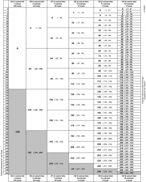
To really understand subnetting, it must be broken down into fundamental parts. This pertains to IPv4, which will likely remain in use for quite some time. The big chart, class B networks:
3nd octet
4th octet
CIDR
Decimal
Wild card
Hosts
3rd Up by
Subnets
00000000
00000000
/16
255.255.0.0
0.0.255.255
65,534
255
0
10000000
00000000
/17
255.255.128.0
0.0.127.255
32,766
128
2
11000000
00000000
/18
255.255.192.0
0.0.63.255
16,382
64
4
11100000
00000000
/19
255.255.224.0
0.0.31.255
8,190
32
8
11110000
00000000
/20
255.255.240.0
0.0.15.255
4,094
16
16
11111000
00000000
/21
255.255.248.0
0.0.7.255
2,046
8
32
11111100
00000000
/22
255.255.252.0
0.0.3.255
1,022
4
64
11111110
00000000
/23
255.255.254.0
0.0.1.255
510
2
128
11111111
00000000
/24
255.255.255.0
0.0.0.255
254
1
256
Class C networks
3rd octet
4th octet
CIDR
Decimal
Wild card
Hosts
4th Up by
SubnetsB
SubnetsC
11111111
00000000
/24
255.255.255.0
0.0.0.255
254
255
256
0
11111111
10000000
/25
255.255.255.128
0.0.0.127
126
128
512
2
11111111
11000000
/26
255.255.255.192
0.0.0.63
62
64
1024
4
11111111
11100000
/27
255.255.255.224
0.0.0.31
30
32
2048
8
11111111
11110000
/28
255.255.255.240
0.0.0.15
14
16
4096
16
11111111
11111000
/29
255.255.255.248
0.0.0.7
6
8
8192
32
11111111
11111100
/30
255.255.255.252
0.0.0.3
2
4
16384
64
11111111
11111110
/31
255.255.255.254
0.0.0.1
0
2
N/A
11111111
11111111
/32
255.255.255.255
0.0.0.0
0
1
N/A
The terms “Class B” and “Class C” networks are outdated. Basically, I broke the chart up along a classful boundary to make it easier to read.
An IP v4 address consists of four octets of binary data. A common example is 192.168.1.154, which in binary numbers looks like this: 11000000.10101000.00000001.11111110. It is converted to base ten numbers (dotted decimal) so that we humans can deal with it. A typical subnet mask seen in many office networks is 255.255.255.0, which in binary looks like this: 11111111.11111111.11111111.00000000. When a router receives a packet, it does something called an “ANDing process.” When a router ANDs, it overlays the subnet mask on the network address and uses the following function: 1+1 = 1, 1+0 = 0 and 0+0 = 0. Thus, in the above example, a router AND would look like this:
Dotted Decimal
Binary Octets
192
168
1
254
255
255
255
0
192
168
1
0
11000000
10101000
00000001
11111110
11111111
11111111
11111111
00000000
11000000
10101000
00000001
00000000
The subnet mask is telling the router to ignore the last octet, thus saving a bit of time and processing power. It may seem very small and insignificant. When considering that routers make sometimes hundreds or thousands of routing decisions in a second, even a small bit of work reduction adds up quickly. Subnet masks allow routers to look at only the layer three network address, ignoring the host portion. This takes advantage of IPs inherent hierarchical addressing system and speeds the process of routing to the proper destination.
Another way to look at it:
IPv4 subnet chart, click for .pdf version
There are three IPv4 address ranges set aside for private (internal) use:
192.168.0.0 to 192.168.255.255 /16
172.16.0.0 to 172.31.255.255 /12
10.0.0.0 to 10.255.255.255 /8
Thus, very large networks can use an internal IP address scheme in the 10.0.0.0 range and have up to 16,777,216 hosts, or 224 addresses minus two, one for the network line address and one for the broadcast address. That would be one giant network clogged with ARP requests, ICMP packets and other miscellaneous multicast messages. A notation of /16 means that 16 bits are used for the network address, the remaining address bits are host bits. A /24 network has 24 network bits and 8 host bits making the available hosts 254.
An example of an efficient network would be a medium market operation with six radio station under one roof. This facility has ten studios and a newsroom using AOIP consoles, a VOIP phone system, an automation system, an office network with an internal file server and exchange server. The number of required hosts on each subnetwork is
Office network, servers and wireless hosts: 78
VOIP phone system: 70
AOIP consoles and nodes: 30
Broadcast automation system: 22
Given IP address: 172.19.0.0 /22
In most instances, office networks are usually installed on one class C segment, that is to say, the network mask is 255.255.255.0. However, in the example above, 254 hosts are not needed on the office network, thus it can be divided in half using the subnet mask of 255.255.255.128, leaving the other half for the VOIP phone system. This subnetting scheme would leave 126 hosts on the office network and 126 hosts on the VOIP network. The AOIP console and broadcast automation system can be placed on another class C segment, using the subnet mask of 255.255.255.192, which would give each subnet 62 hosts. All subnets would have room to expand. Each subnet is isolated from the others by a router. The office subnet contains the gateway to the internet, usually .1 or .126 (first or last) IP address.
That would look something like this:
Office network
Line address
First available
Last available
Broadcast
Subnet mask
172.19.0.0
172.19.0.1
172.19.0.126
172.19.0.127
255.255.255.128
VOIP phone system
Line address
First available
Last available
Broadcast
Subnet mask
172.19.0.128
172.19.0.129
172.19.0.254
172.19.0.255
255.255.255.128
AOIP consoles and nodes
Line address
First available
Last available
Broadcast
Subnet mask
172.19.1.0
172.19.1.1
172.19.1.62
172.19.1.63
255.255.255.192
Broadcast Automation system
Line address
First available
Last available
Broadcast
Subnet mask
172.19.1.64
172.19.1.65
172.19.1.126
172.19.1.127
255.255.255.192
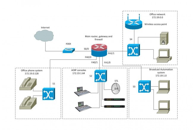
That keeps the network segments small but has room to grow. This is a diagram of a converged network:
Radio Broadcast Facility converged network
With a setup like this, reliability is the key to a happy life. The router should be a good Cisco product with four or more Fast Ethernet ports. A second way to do this would be to have four routers plugged into a distribution switch and use OSPF to route between subnetworks. The switches should also be a good Cisco product, which can take advantage of port security options and QoS on the VOIP and AOIP segments. VOIP systems usually require Power over Ethernet (POE) ports, thus that switch can be specialized for that purpose.
Many AOIP systems want to see Gigabit switches or at least Fast Ethernet switches with Gigabit or better backplanes. Any AOIP STL system can be connected to the AOIP network along with other things like AOIP remote broadcast and studio telephone solutions.
Many WLAN access points can be configured as a network router and DHCP server for wireless hosts.
The largest users of the public (i.e. internet) network would be the VOIP phone system and office network. The broadcast automation network may also be a if voice tracking or other program delivery over WAN is used.
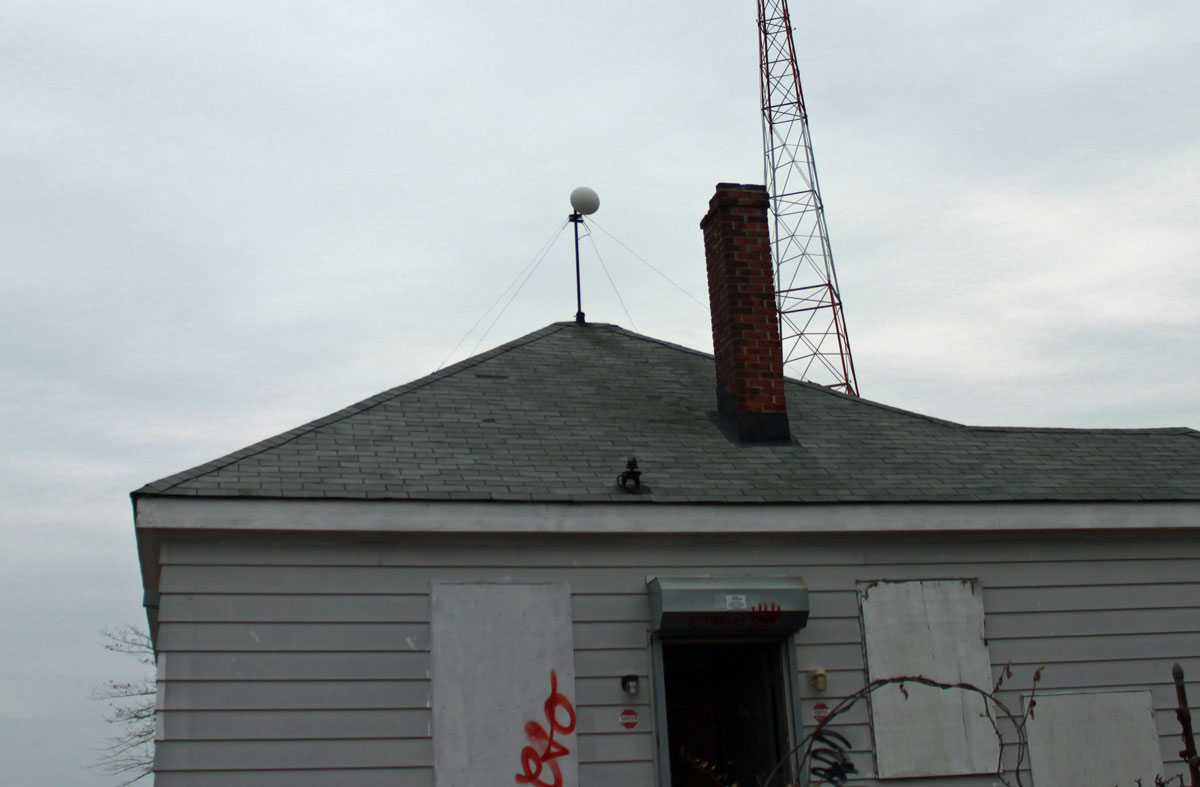
After a bit of delay, we were able to return to the WICC transmitter site to install the Wireless LAN link. The installation was pretty straightforward. The studio unit was mounted on an existing STL tower on the top of the elevator room, the transmitter unit was mounted on an existing pipe on the roof of the transmitter building.
M5 Nanobridge mounted on transmitter building with RADOME
I included RADOMEs for a couple of reasons; first, there is a lot of critters around of the two-legged and winged kind. The upright two-legged critters may be attracted to the signal-strength lights at night. This unwanted attention could invite the juvenile delinquent’s bored teenagers to throw various objects found laying around on the ground at the antenna, damaging it. The winged type critter may be inclined to view the feed horn as a good nesting location. The other reason is this site gets a lot of rain, wind, ice, and snow, therefore the RADOMEs afford some protection against the weather.
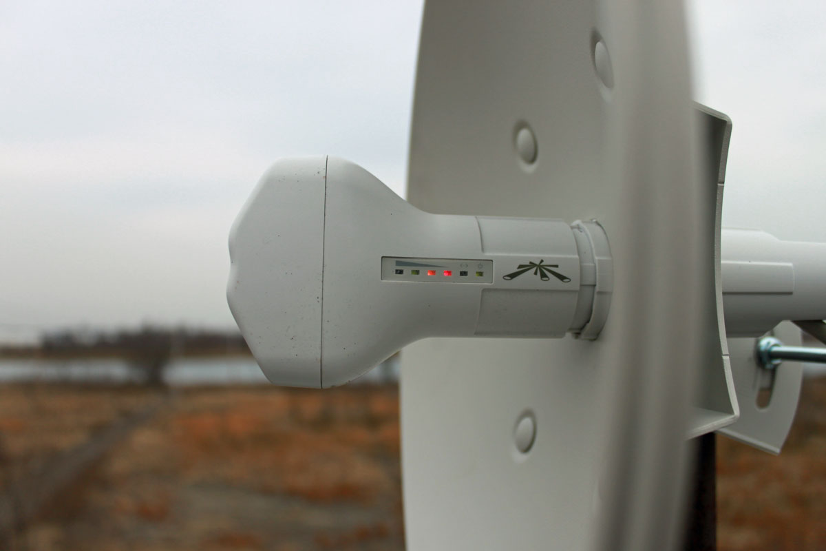
Aiming the antennas was pretty straightforward, but requires at least two people. Using landmarks, we aligned the dishes in the general direction of each other. Both ends of the system were turned on and we had a -89 dBm signal path, and somewhat surprisingly, the radios linked up and my laptop grabbed an IP address via DHCP. Using the signal strength meter on the side of the antenna, each dish was peaked in turn:
M5 Nanobridge Antenna signal strength meter
Then, somebody on either end went below and looked at the signal strength screen on the web interface while the other end peaked. In the end, we had about -65 dBm signal strength, which is somewhat less than the -58 dBm predicted. I think we can do better, so on the next clear day, I am going to peak the signal again.
The data rate initially reported was over 100 MBPS, however, once I started transferring files back and forth, that dropped to about 50 MBPS. If it is raining, that rate drops to about 35 MBPS, which is still far above what we need this link to do. As a test, I streamed a youtube video, downloaded a Windows update, loaded several web pages, and checked my email simultaneously. There were no issues with the data rate while those tasks were being preformed.
It is quite amazing to me that these little inexpensive radios can work so well. My boss thinks that they will be blown up by lightning during the first thunderstorm of the season. I don’t know. There are several of these units have been installed at mountaintop tower sites and have been working for several years without issue.
Next step, installing the IP cameras and warning signs on the fence, setting up the monitoring software, etc.
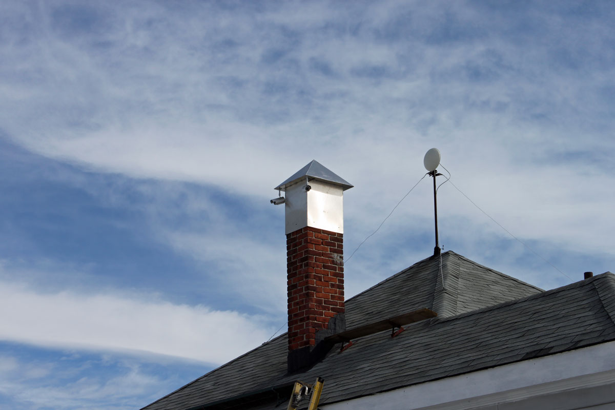
Transmitter site security cameras
Cameras mounted on old chimney platform. This is the first set of cameras covering the south, north, and west approaches. A fourth camera will be mounted on the back of the building covering the east approach. Then, under the eves’ cameras will be mounted on all four corners of the building and the generator shed. If anything moves, it will be recorded.
Wireless IP Ethernet (802.11) technology has been around for a while. Many know it as “WIFI” but you could also call it “WLAN” or something similar. Like many other Ethernet technologies, WLAN relies on a spoke and hub connection system. The hub is the wireless access point or router and the individual hosts (PCs, tablets, phones, etc) are the end point for each connection. In a wired network, it is usually some type of switch that forms the center of the network data distribution system.
With a wireless mesh network or ad hoc network (802.11s), each wireless device can connect to any other wireless device within range. In this type of peer-to-peer network, there is no central access point, although something can act as an internet gateway or there can be several gateways. This type of topology functions much like the public network (AKA the internet), where there are many different paths to anyone (major) destination. If any one of those paths goes down, another route is quickly found.
This technology was developed by several vendors for military communications systems and for OLPC (One Laptop Per Child) programs in Africa and other places. Each link acts to extend the boundaries of the network, thus the more users there are, the more useful the network becomes.
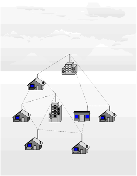
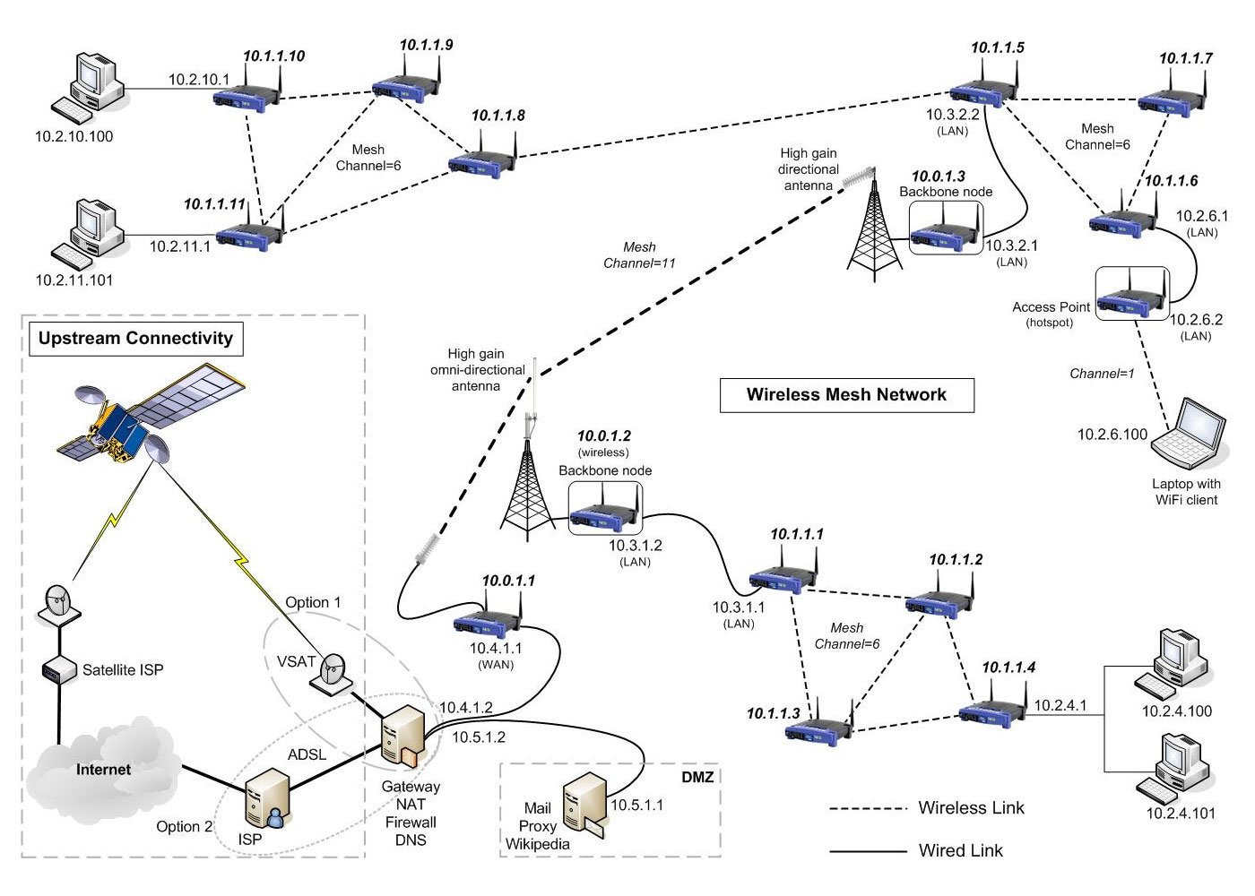
Wireless Mesh Network diagram
Advantages of mesh networking:
Networks are self-forming; once the nodes are configured and can see other network nodes, the network automatically forms
Networks are self-healing; if one node drops offline, traffic is automatically routed to other nodes. If the node comes back up, it is included back into the network
High fault tolerance; in areas where many nodes exist and can see each other, the failure of any single node does not affect the rest of the network
Low cost to deploy; mesh networks use standard off-the-shelf WLAN (802.11) devices. The choice of software will dictate which hardware will work the best
Crowd-sourced infrastructure; as each network node is owned by an individual, the cost and responsibility is shared among the community
Several specific routing protocols have been developed for the network side of the system. Hazy Sighted Link State Routing Protocol (HSLS), BATMAN, OLSRHWMP and others. These work well with the existing 802.11 a/b/g wireless network hardware currently available.
On the host side, a good IBSS-capable wireless network adapter is needed, which many of the newer ones are. Several of the software programs have lists of WLAN adapters that work with their software. Open Garden is a free App for Windows, Mac OSX, and Android, and they are working on an iOS version. This leaves out certain devices like tablets and iPhones for now.
Since existing wireless adapter drivers do not yet support mesh networking, usually an additional piece of software is needed. There are several interesting ones, including HSMM-MESH, which was developed by Amateur Radio operators. Open-source programs for Linux, Free BSD and other are available as well as commercial versions for Windows.
I was thinking that this might be useful for broadcast applications. For obvious reasons, this type of system would work best in densely populated urban and suburban areas, which is exactly the type of area in which LPFM licenses might be hard to come by. For those who do not have the time or wherewithal to apply for an LPFM license, or for those that simply don’t get a license due to scarcity of available channels, this could be a great way to cover a neighborhood or section of a city. The more people participate in the mesh network, the stronger the network becomes. Additionally, by using FCC type accepted part 15 FM and AM transmitters as broadcast nodes, carrier current transmitters, and leaky coax systems, the presence of the mesh network can be advertized to potential listeners, including directions on how to take part.
Wireless mesh network example, courtesy of Meraka Institute
Wireless LAN bridges or broadband internet connections can act as a backbone between distant nodes.
For bandwidth efficiency sake, AOIP services should be limited to multicast addresses.