Measuring FM Harmonics

Anytime a new transmitter is installed or major changes to an FM transmission system are implemented, the performance measurements described in FCC 73.317 should be completed to ensure no interference to other radio services. This is becoming a larger issue with the advent of LTE and 5G mobile data. These services along with E911 and other mobile services are often co-located at FM transmitter sites.

The FCC stipulates that emissions removed from the carrier by more than 600 KHz must be attenuated 80 dB below the carrier. These days, that is not enough. We have had issues with older tube-type transmitters interfering with cellular and mobile data service, even though they met or were far below the FCC specification. The first in, first out rule also didn’t seem to matter either. Those mobile phone providers paid a lot of money when they purchased chunks of RF spectrum at auction, and the FCC will side with them if there is any dispute.

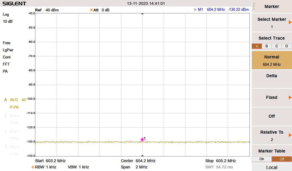
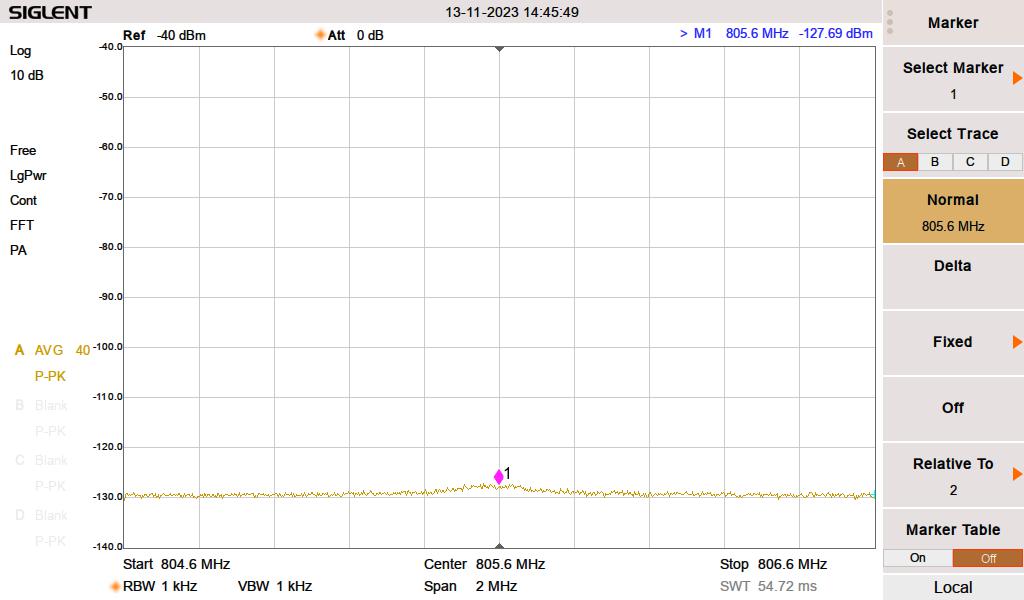
Having a record of measurements that show compliance with the FCC regulations can go a long way in heading off any future problems. I make measurements out to the 10th harmonic.

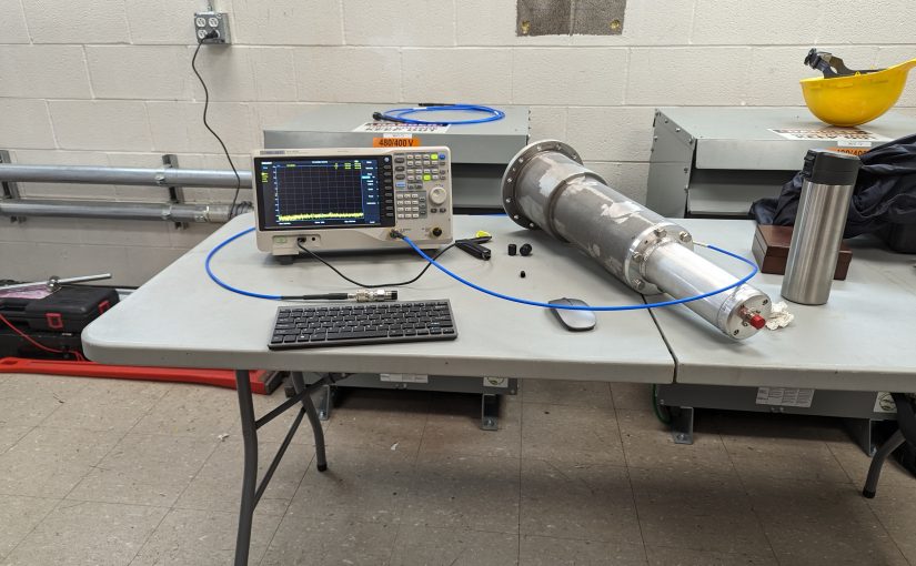
To get the best results, I have been using a couple of high-pass filters from Mini-circuits.

Mini-Circuits NHP-200+

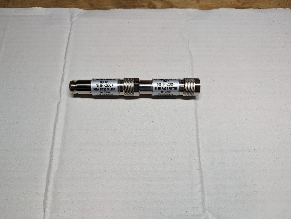
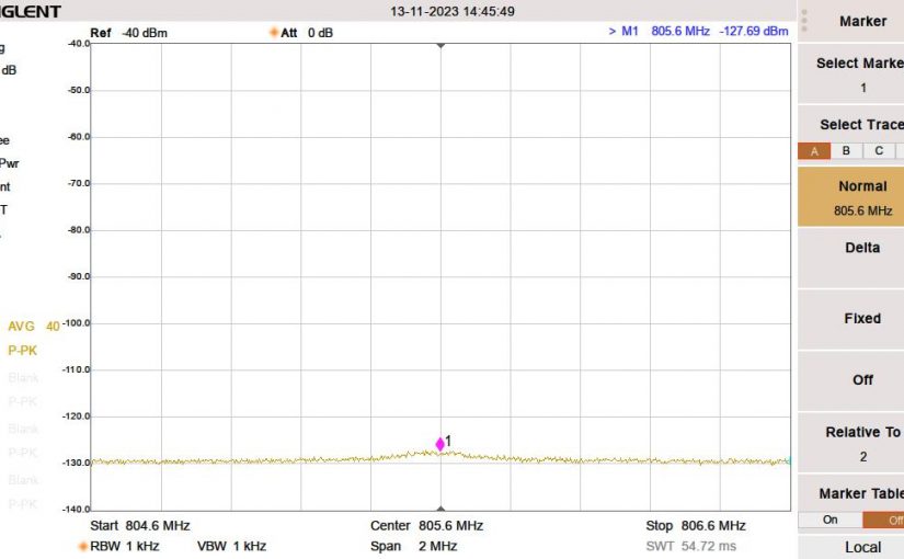
These attenuate the carrier power seen by the spectrum analyzer by approximately 90 dB depending on the frequency. That allows the instrument noise floor to be lowered to -130 dB which should be well below any receiver noise floor being used by other wireless services.

100.7 MHz no HPF
100.7 with two HPF-200+ High Pass Filters

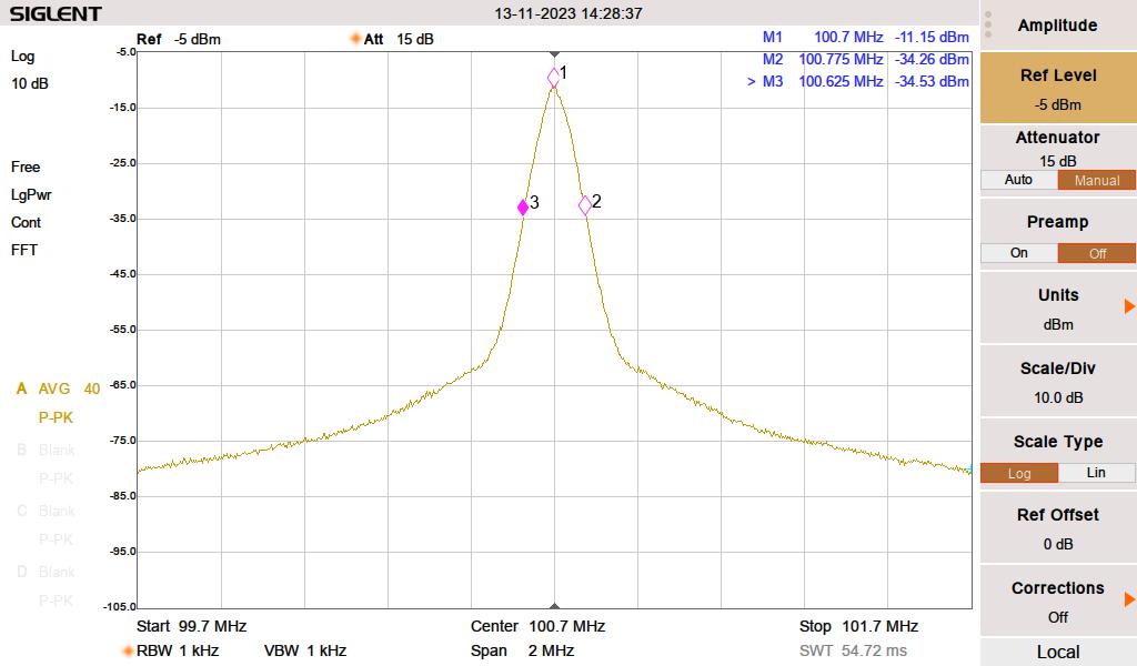
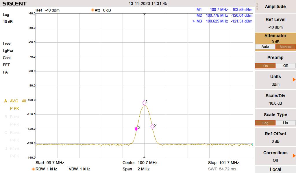
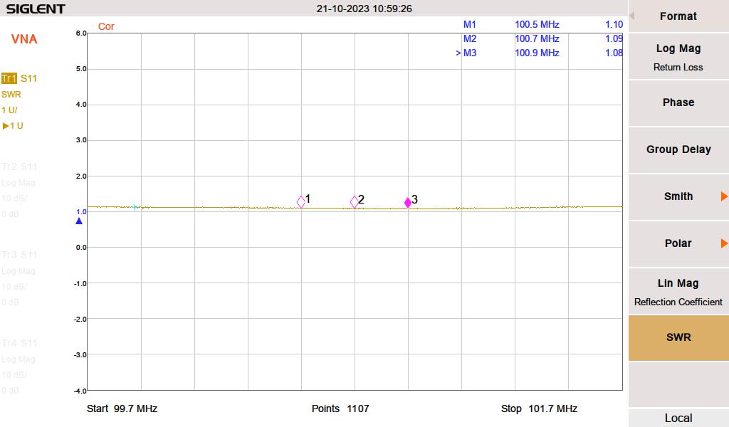
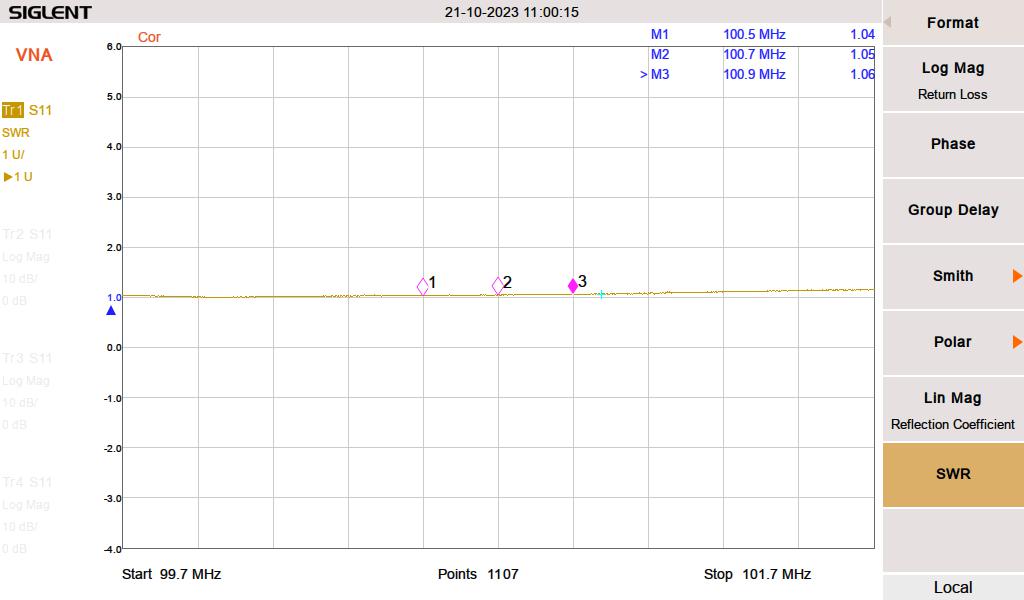
The carrier is attenuated by 92.44 dB. The rest of the measurements are made with the attenuation set to zero and the preamp turned on. For the lowest FM frequency, 88.1 MHz, the filters are on the edge of their shoulder at the 2nd harmonic. I measured the return loss and found that they matched the manufacturer’s datasheet.

Mini-circuits HPF-200+ X 2, 176 – 216 MHz S21 Return loss

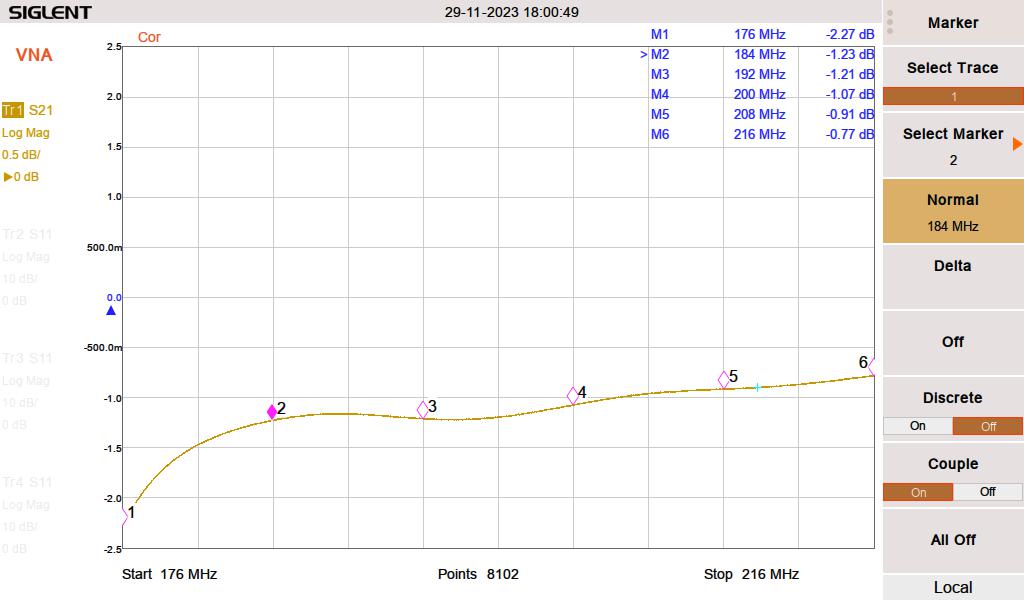
That loss is counted as attenuation for the second harmonic. For the rest of the harmonics, I used 0.5 dB attenuation, which represents connector loss. I could have also measured the cable loss at each harmonic, but that seems unnecessary, given several of the readings were below the noise floor.

To speed things along, I made this handy Excel spreadsheet, which does all of the calculations for me:

FM harmonics spreadsheet

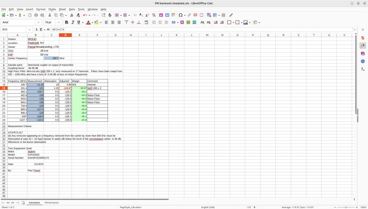
A copy of that spreadsheet can be downloaded: FM Harmonic template

Once completed, I printed a copy and put it with the station maintenance log at the transmitter site.

Some More TV work

GatesAir contracted me to go to Utica, NY, and do some repair work. WKTV has a ULXTE-50 UHF transmitter which burned out an RF elbow between the UHF combiner in cabinet 1 and the UHF low pass filter for cabinet 1.

Burned-out RF parts
3 Port UHF combiner, cover removed for cleaning

There was a bunch of burned debris in the bottom; little bits of melted metal and plastic.

Bottom of UHF combiner

We first vacuumed out as much stuff as we could get. Then used an air compressor to blow the rest out and wiped everything down with clean rags and Windex.

Once that was done, the unit was reassembled and reinstalled in the transmitter. A new elbow, UHF low pass filter, and direction coupler were installed and the transmitter powered back up.

WKTV RF channel 29, 708 KW ERP, 990 foot (302M) tower

The transmitter site is actually located north and slightly west of Little Falls, NY. The station has been on the air since 1949 and the original GE transmitter is still in the garage. It was difficult to squeeze in and get a look at the transmitter, however, the operator’s console was out in the open:

GE TV control operator’s console, circa 1949

In most places, this would have been thrown out years ago. Now, it is a museum piece. Lots of interesting history in the Wikipedia article, too.

The Rhode and Schwarz THR9 transmitter

Part II of II

This thing is on the air! There are still some tidying-up things to finish, but it is up and running and sounds great! Here are some pictures of various stages of the installation work:

Making harmonic measurements

The filing cabinets hold manuals and spare parts. There is not a lot of room left in this building, so workspace is at a premium. The filing cabinet on the left needs some Windex and elbow grease.

Main disconnect and conduit to 400-volt transformer
Outdoor coolant run
3/0 cables, 240-volt input to Hammond HPS Sentinal K transformer

The transformer does not have a neutral reference to the power company. The neutral for the transmitter is derived from the Y output connection. The transformer is also designed to suppress harmonics from non-linear loads like switching power supplies.

Wiring in Square D I line panel
Square D I-line panel rated for 600 volts
#2 SOOW cable feeding upper and lower sections of transmitter
Wiring to disconnect switch on transmitter
Pump station during system fill
Heat exchanger

The wiring on the pump station and heat exchanger needs a little more work. The client wanted to get this on the air as soon as possible because they are in a book and were running at 50% power. Once things calm down a bit, I will put the backup transmitter on for an afternoon and properly dress the wires.

FM modulation analysis

I found this FM modulation analysis function on my spectrum analyzer very useful. The station deviates slightly more than the allocated 75 KHz because of a subcarrier. Overall, it looks good. I measured the harmonics out to the 10th harmonic, most of them were in the noise floor. A few made a slight appearance, but well within FCC tolerances. It is important to document this, as this site has colocated cellular carriers and several E911 services.

FCC part 73.317 states:

(d) Any emission appearing on a frequency removed from the carrier by more than 600 kHz must be attenuated at least 43 + 10 Log10 (Power, in watts) dB below the level of the unmodulated carrier, or 80 dB, whichever is the lesser attenuation.

47CFR 73.317
WHUD fundamental
WHUD fundamental with two Mini-Circuits NHP-200 high pass filters installed

The rest of the harmonics were measured down to -130 dB with the two NHP-200 high-pass filters in the circuit. The 3rd, 4th, 5th, 6th, and 8th harmonics were unmeasurable. The 8th, 9th, and 10th made slight appearances.

WHUD 6th Harmonic, noise floor
WHUD 8th harmonic makes a little appearance
Main antenna VSWR
Antenna VSWR according to the transmitter directional coupler

Pretty close, the VNA was inserted at a patch panel, which is the last thing before the transmission line leaves the building. The transmitter goes through an ERI switchless combiner, which probably gives it a slightly better load.

Backup antenna SWR

Aside from the finishing details, I need to keep an eye on this for a week or so and top off the Heat Transfer Fluid as needed. It takes a bit of time to get all of the air out of the coolant loop. Another thing; the operating pressure on this is 4 Bar, which is almost 60 PSI. That is higher than other liquid-cooled transmitter systems I have installed before.

TV sweeps

We have been really busy this fall working on multiple projects plus the day-to-day tasks. One thing that is always fun; sweeping antennas with a VNA.

In this case, WVIT Hartford, CT needed to repair a leaking transmission line section just below the antenna. To ensure that there would be no problems with return to the air at full power, we did a before sweep and after sweep.

WVIT is the ATSC 3.0 lighthouse station for the Hartford Market. FCCinfo.com has the station listed as ATSC 3.0.

WVIT Tower, Hartford CT

The WVIT tower is 1,100 feet tall and is located on Rattlesnake Mountain near Farmington, CT. Most of the other Hartford TV stations are on the same hill.

Tower crew, hitching a ride to the top
Selfie; return loss looks good

It is always interesting to see new places and meet new people. This site has an auxiliary TV studio, which they were using during COVID.