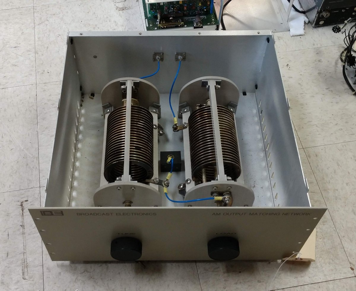
Occasional reader Scott asked for a picture of the inside of a BE AM output tuning network. I figured it might be helpful to make a short post about it.
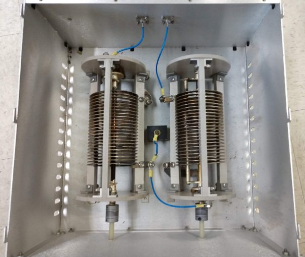
These things are pretty simple; a T network with a capacitive leg to ground.
This particular unit is for 1230 KHz. I believe the capacitor is frequency determined and they may also use larger inductors for lower frequencies.
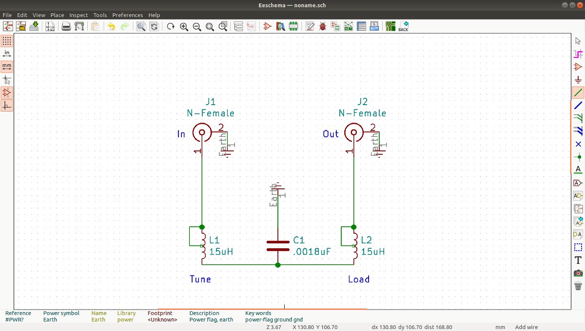
The inductors are Kintronic LV-15-20 (15uH 20 amp) and the capacitor is 0.0018 uF CDE 6KV 5.6 amp.
The issue with this particular unit is dirt. The inductors have round metal plates that roll along the inductor coil to make the variable inductor tap. Dirt has accumulated on the coil turns and on the inside of the plates. This, in turn, causes arcing anytime the Tune or Load controls are moved. A thorough cleaning should take care of the problem.


Paul…Thanks for the pictures..always wondered how the lay out of the box was…
A fellow linux user? Awesome!
Scott, no worries. If one person asks a question, likely several others are thinking it.
Oliver, I have been a long time Linux user. A few years ago I paired my windows machines down to one laptop. Everything else in my life runs on Linux.