AKA: Tube amp part II
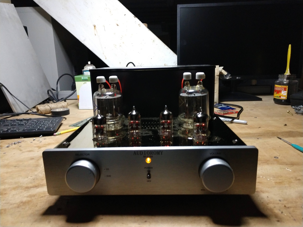
I have been fooling around with this amplifier for a month now and I have to say, it is rather fun. There are a few hazards when purchasing Chinese HiFi (ChiFi) equipment.
The first thing to note; several places such as Ebay and Amazon list this as a single-ended class A amp. That is not true, it is a double-ended class AB amp. I confirmed this by measuring across the two sections of the output transformer.
The second thing to note; this amp came wired with a fuse on the hot side of the AC mains and the power switch on the neutral. Switched neutral (AKA earth, return or ground) wires are a hazard, so I rewired it, putting the switch after the fuse on the hot side after the fuse. Another safety thing, the edge of the metal chassis was not de-burred. I took a flat file to it and removed the burr, thus avoiding any future lacerations.
Finally; there is no manual provided with this unit. There are a few sets of instructions on how to re-bias after tube replacement which is technically correct but not the best way to go about it. Those instructions direct the user to solder a low-value resistor from cathode to ground and then measure the voltage drop on that resistor to calculate plate current. While this is a valid way to deduce plate current, the power output tube has two tubes in one envelope and the cathodes are tied together. The plate current can be calculated for both sides, but there is nothing indicating that the two sides are balanced and one of the tubes can red plate. This was also noted in those instructions found online.
That being said, I thought I could type up a set of directions that are more suited for this amplifier. But first, read this dire warning about working with High Voltage:
This amplifier has lethal voltages present during operation. It is possible that lethal voltages can be stored in certain components for days after the amplifier has been turned off and disconnected. By removing the protective covers, those components will be exposed and you may come in contact with them if you are not careful.
If you are planning to service this amplifier, it is vital that you have basic electronics and electrical knowledge. This includes all applicable safety procedures for working on high-voltage components.
If you do not have this knowledge, please bring this amplifier to a qualified electronics technician or repair shop for service.
I am not responsible for any injuries or damage suffered to yourself or others if you decide to undertake repairs to this equipment.
I acquired a few of these Ulyanovsk GU-29 tubes and decided to try them out. The maximum plate dissipation for this tube is 40 watts with bulb temperature of 175°C and ambient temperature of 20°C. I measured the bulb temperature at 142°C and the temperature in my living room ranges from 20ºC to 32ºC (68ºF to 90ºF). I could, in theory, bias these tubes for a higher plate dissipation, if I wanted to.
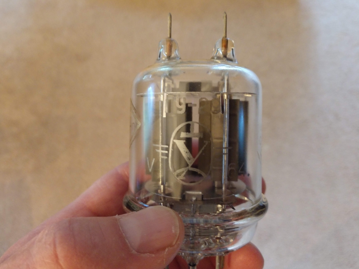
I asked my Russian friend what the assembly line person or factory manager might think if he or she knew that the tube made in their factory would end up being used in a home audio amplifier owned by a guy in New York. She said, “They would have a stroke.” Ulyanovsk had and still has a heavy military presence, thus they likely assumed that all their products would be used by the Soviet Navy or Army.
Being that this particular tube sat around in a warehouse for 55 years, it was slightly gassy. When I first turned the amp on, there was a distinctive pink glow and a couple of small internal arcs. It probably would have been a smart idea to light up the filaments for several hours before applying plate voltage. Unfortunately, I had that idea after I’d already energized the amplifier. In any case, I increased the bias and reduced the plate current. After a while, things settled down and I got to work re-biasing the amplifier.
To re-bias the amplifier after new tubes have been installed, some initial data needs to be gathered. Basically, this procedure involves measuring the resistance of the plate circuit, then measuring the voltage at the output of the plate voltage supply and the voltage at each of the plate terminals on the power amp tube. The plate voltage on this amplifier is +460 DC or so voltage above ground potential. Obviously, this is a dangerous voltage and if you are not familiar with working on high voltages, do not attempt this procedure. The best way to measure these test points is to use clip leads; turn the amp off, let the capacitors discharge, place the clip leads on the appropriate test points, turn the amp on, make the measurement, then turn the amp off, repeat as necessary.
After the replacement of the power tubes (V-5 and V-6), the bias for those tubes should be checked and adjusted as follows:
A. To measure plate dissipation as set by the factory, perform the following steps:
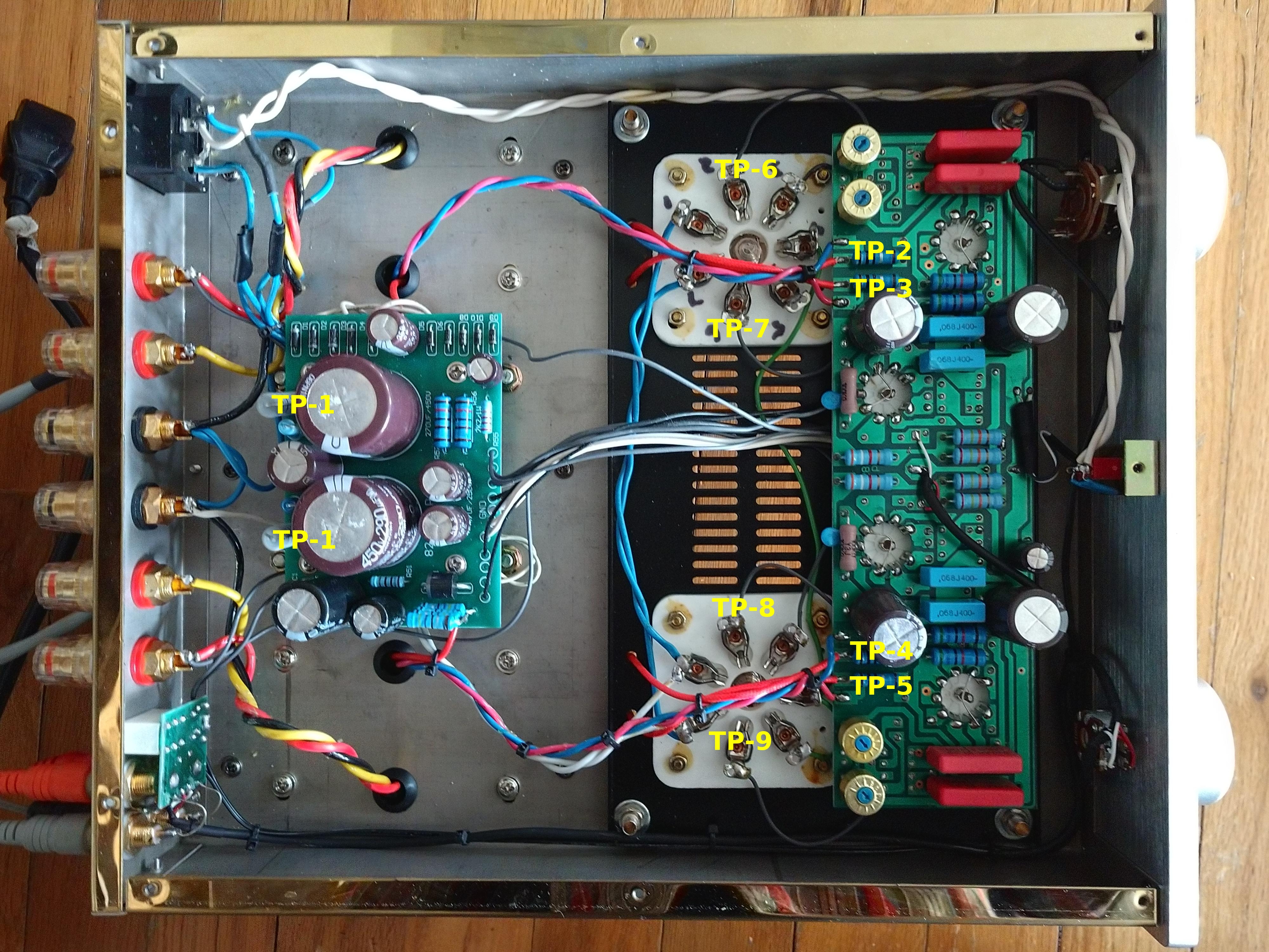
1. With the amp completely turned off and disconnected from the AC mains, remove the bottom cover. Ensure that the large power supply capacitors are discharged to the ground. With an accurate ohm meter, measure from the exposed lead on L-1 (TP-1) on the power supply board to the input to the anode resistor (R-21 or R-22 in the schematic diagram (TP-2, TP-3, TP-4, TP-5)) for each tube (four measurements total). Make a note of those measurements. For reference, my amp measured between 163 to 165 ohms.
2. Reconnect the amp to the AC mains and turn on the power (be sure to read the dire warning about high voltage above). With an accurate DVM, set to DC volts scale, carefully measure the voltage on the exposed lead of L-1 on the power supply board to the ground, and make a note of it. This is the B+ voltage for the amplifier. Carefully make another measurement between the input of the anode resistor (R-21 or R-22) and ground (four total measurements, likely to be the same), this is the plate voltage for the power tubes. Make a note of that as well.
3. Subtract the plate voltage from the B+ voltage. For my amp, this was 462 VDC – 458 VDC = 4 volts. This can also be measured between TP-1 and TP2 through TP-5 See charts 1 and 2 below. This is the voltage drop. Using ohms law, calculate the plate current for each section of the amp:
Voltage drop ÷ resistance = plate current or 4.17 VDC ÷ 163.2 ohms = 0.0255 amps (25.5 ma) plate current.
Using ohms law, calculate the plate dissipation for ½ of the power tube:
Plate voltage × Plate current = Plate Dissipation or 458 V × 0.0255 amps = 11.7 watts.
Add both sides of the tube together for the total plate dissipation.
Chart 1: Left power tube, V-5
| Test points | Resistance | Plate voltage (TP-2/3 to gnd) | B+ (L1 or TP-1 to gnd) | Voltage drop | Plate current | Dissipation |
| TP-1 to TP-2 | 163.2 ohms | 458 VDC | 462 VDC | 4.17 VDC | 25.5 ma | 11.7 watts |
| TP-1 to TP-3 | 163.9 ohms | 458 VDC | 462 VDC | 4.16 VDC | 25.3 ma | 11.6 watts |
The total power dissipation for V-5 is 23.2 watts or 77% of the maximum for the stock FU29 tube. That is slightly above the commonly recommended safe range of 70% of the maximum, but it is tolerable.
Chart 2: Right power tube, V-6
| Test points | Resistance | Plate voltage (TP-4/5 to gnd) | B+ (L1 or TP-1 to gnd) | Voltage drop | Plate current | Dissipation |
| TP-1 to TP-4 | 164.4 ohms | 458 VDC | 462 VDC | 4.23 VDC | 25.3 ma | 11.6 watts |
| TP-1 to TP-5 | 164.8 ohms | 458 VDC | 462 VDC | 4.14 VDC | 25.1 ma | 11.5 watts |
The total power dissipation for V-6 is 23.1 watts or 77% of the maximum for the stock tube.
B. When replacing the power tubes, it is recommended that they be replaced in kind in pairs.
Step 1: Increase the tube bias (measured on pin 2 or 6 of the power tube) to -25 VDC and check the plate voltage drop on both tubes. Increasing the bias will reduce the plate current and thus the plate dissipation. This will be noted as a decrease in the voltage drop. A good starting set point would be 50-60% of the normal factory plate current (Vd ÷ Plate R) setting. The voltage drop can be measured directly by connecting the positive lead to TP-1 and then measure TP-2 to TP-5 with the negative lead. Use clip leads, placing them on the test points with the amplifier turned off. Be extremely careful; these test points are +460 VDC above ground when the amp is energized. Read dire voltage warning above.
Step 2: Turn off amp, discharge power supply capacitors, replace tubes.
Step 3: Allow the new tubes to burn in for approximately 3-5 hours with reduced plate dissipation, make sure that the amplifier is connected to a suitable load on the speaker output terminals.
Step 4: With the DVM connected to TP-1 and TP-2, slowly bring the bias down until the plate circuit voltage drop approaches the values for the old tube. Repeat procedure for each plate circuit (TP-1 to TP-3, TP-1 to TP-4 and TP-1 to TP-5). Recalculate plate dissipation. Be sure not to exceed plate dissipation of the tube! It is best if the tube is biased to run at about 70-75% of the maximum plate dissipation.
Step 5: With the amp fully warmed up, turn out all lights and observe the plates of both tubes for any signs of red plating.
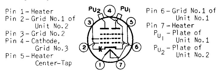
Step 6: Carefully measure the balance between the two plate outputs of each tube by placing the DVM leads on TP2 and TP3 for V5 and TP4 and TP5 for V6. Alternatively, the test leads can be placed directly on Pu-1 and Pu-2 of the power tube under test. Between these test point pairs, the DC voltages should be zero or close to it. Note; there will be some fluctuations in the hundredths or thousandths volt ranges. Very, very carefully, adjust the bias control pots until the voltmeter reads zero or as close as you can get to zero.
Step 7: Recheck the plate dissipation for both sides of the tube, make sure that they are closely matched and not exceeding the maximum plate dissipation for the power tube in use.
I discovered several things during this process; it is very easy to red plate one side of the tube while adjusting the bias controls. Fortunately, I noticed this right away and was able to stop the red plating quickly. The Ulyanovsk tubes seem none the worse for wear. As Alex Ovechkin says “Russian machine never breaks.”
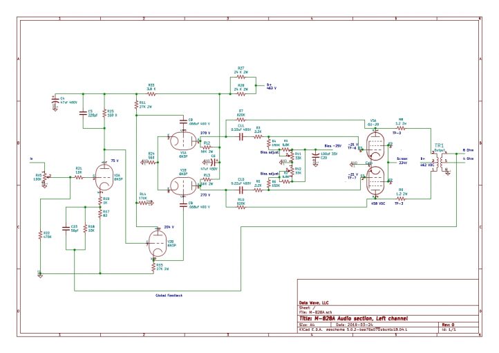
Next, the schematic diagram I posted previously is not correct for this version amplifier. There are two bias voltage controls, one for each grid. There is no balance control, the tubes are balanced by making very careful adjustments to one or the other of the bias controls. Updated schematic diagram:
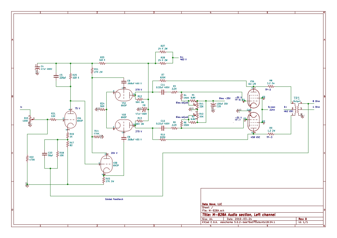
When the amplifier is properly biased and balanced, the distortion figures should be very low, less than 0.5 to 1% THD at full power. It makes a big difference.
The point of all this is to 1) have fun, 2) perhaps learn something about tube (or valve) circuits and 3) listen to really clean, good-sounding audio.