Emergency transmitter replacement

Bad weather or other disasters can strike any time of year.  Around these parts, the most dangerous weather events occur from early spring through late summer.  In the past twenty years or so, we have had tornadoes, hurricanes, micro bursts, flooding events and so on.  All of that got me thinking about what would happen if a tower came down, or a transmitter building was destroyed by fire, wind, water, etc.

If past events can predict future performance, there would ensue a mad scramble to replace damaged equipment and or get some type of temporary antenna into service.  That is what happened in great City of North Adams, Massachusetts when the tower that held the cell carriers, the 911 dispatch, and the local FM radio station came down in an ice storm.  Fortunately, we had a single bay Shively antenna at the shop that we trimmed up and installed on a temporary pole with 200 watts TPO.

That will cover the city of license, provided there is electricity…

What if there where an event that was so devastating that the electrical power would not be restored for months?  Think about hurricane Maria in Puerto Rico.   After that event, the infrastructure was so devastated that there was not even the possibility of getting a fuel truck to deliver diesel for the emergency generators at the hospital in San Juan.  It can happen.

With that in mind, I began poking around and thinking about how I would get something back on the air.  In the face of massive disasters, AM and FM radio is still the most effective way to communicate with the general public.  Radios are still ubiquitous in homes, cars and businesses.

Bext 30 watt exciter
Bext 30 Watt FM exciter

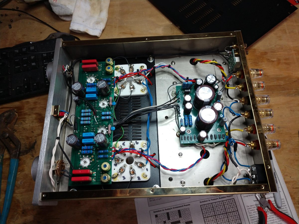
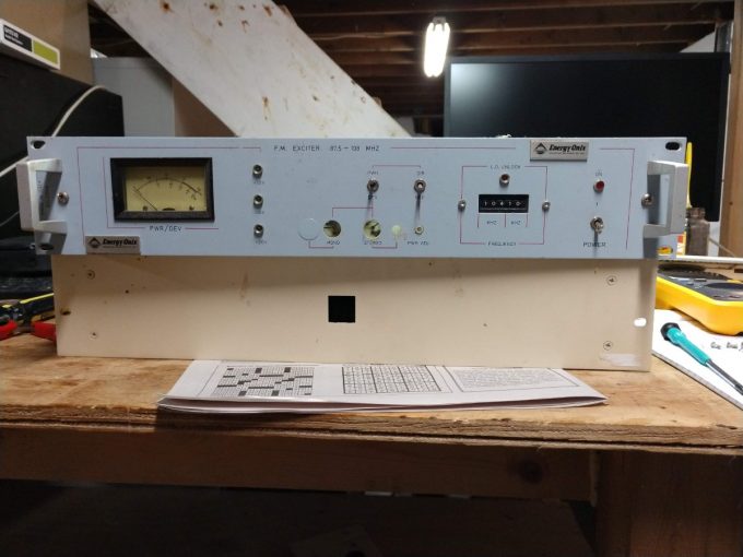
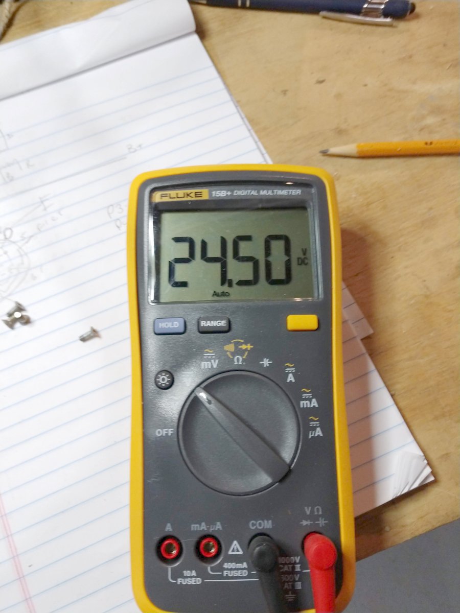
In a short period of time I came up with a couple of solutions.  First, the frequency agile Bext exciter uses a single solid state rectifier feeding 24 volts to the power supply board.  The audio input includes a mono balanced line level input which can be fed by a computer sound card or some other simple source.

Bext 30 Watt FM exciter power supply

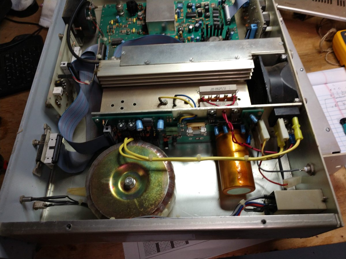
From there +12, +15 and +20 VDC are created to run various circuits.  The heat sink cooling fan is the only thing that runs on 120 VAC, which is old and I might replace with a 24 VDC unit.

Bext 30 Watt exciter power supply voltage

The power output is about 22 watts, which is not bad.  That will certainly get out well enough from a high spot and provide good coverage when the power is out because all the other in band RF noise generators will be off.

6 volt, 435 Ah batteries

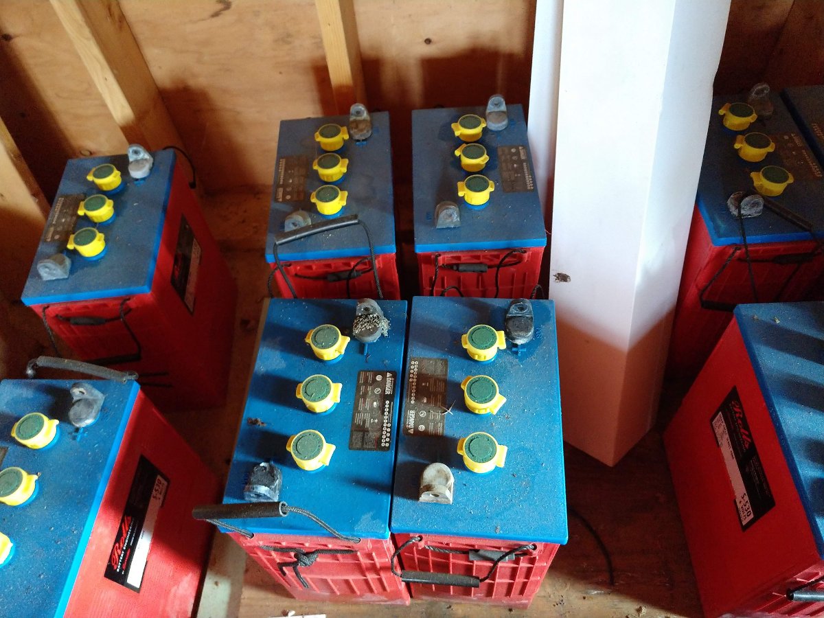
Then I though about the deep cycle batteries in my barn.  These 6 volt, 435 Ah units have been around for a couple of years, but last I checked, they still held a charge.  Other deep cycle batteries from things like golf carts, fork lifts, campers, boats etc could also be pressed into service.  The point is, 24 VDC should not be impossible to create.

To keep a charge on the batteries, this solar panel will work:

225 Watt, 36 volt solar panel

This setup would require some sort of 24 volt DC charge controller, which I found on Amazon for less than $15.00 US.  This charge controller has selectable 24/12 VDC output and also has two USB ports which would be handy for charging hand held devices.

I measured the power draw while the exciter was running 20 watts into a dummy load, it draws 120 Watts.

The final part would be some sort of antenna with transmission line.  For this situation, a simple wire center fed dipole hung vertically would work well.  This can be fabricated with two pieces of copper wire and a few insulators.

Simple dipole antenna

The lengths of each wire can be calculated as follows:

Approximate length in feet: 234/f (MHz)

Approximate length in inches: 2808/ f (MHz)

Approximate length in cm: 7132/f (MHz)

For the FM band, maximum length of wires needed will be 32 inches (81 cm).  Insulators can be made of anything that does not conduct RF; PVC, ABS, dry wood, dry poly rope, etc.

Emergency FM band dipole
Emergency FM band dipole, cut to 88 MHz, lowest FM frequency

I recommend to cut the wires slightly long, then trim little bits off of each end while watching the reflected power meter on the exciter.  To keep RF from coming back down the shield of the transmission line, make 8-10 turns, 6-8 inches in diameter of coax as close to the antenna as possible and secure with a wire tie.  This will create a balun of sorts.

My emergency FM kit consists of:

  • Bext Frequency agile exciter
  • 30 feet, RG-8 coax with N male connector on one end
  • 4 ten foot RG-58 BNC male jumpers
  • 1 four foot LMR-400 N male jumper
  • Dipole antenna, cut long
  • Solar charge controller
  • Small basic tool kit; hand tools, plus DVM and soldering iron
  • Power cords, extension cords
  • 300 watt 12VDC to 120VAC inverter (pure sine wave)
  • 20 feet audio wire
  • Various audio connectors; spade lugs, XLR male and female, RCA, 1/4 TRS, etc
  • Various RF connectors; PL-259, N, BNC, etc
  • Bag of 12 inch wire ties
  • 3 rolls of 3M Scotch 88 electrical tape
  • 100 feet of 3/8 inch poly rope

This is all kept in a sturdy plastic storage bin from the Home Depot.  If needed, the batteries and solar panel are stored in the barn along with an assortment of other goodies.

Will it ever be needed?  Well,  I hope not.  However, it is much better to be prepared to restore services than wait for somebody to show up and help.  Sitting around complaining about the government does not relieve those people in need during and after a disaster.

Tube Amp

I have dipped my toe into the world of tube (or valve) audio.  The first thing that I learned was that in general, tube amps are expensive.  It seems that the least expensive amps run about $1,000 US, and from there it seems the sky is the limit.

There are a number of less expensive Chinese versions floating around, most of the tube audio experts call them garbage.  Myself; I am not so sure.  There are also a lot of somewhat dubious claims made by the same experts about speaker cables, AC power conditioning, and so on.

I was going to build a single-ended tube amp based on the KT88 design found here:

That is a whole series of videos, eighteen in all I think, on the design and construction of a single-ended KT88 audio amp.  If you have the time, well worth it to watch.

Then I decided that I really do not have a lot of time for that and I just wanted to try a tube amp and see if there is really that big of a difference.  Thus, I purchased one of the Chinese designs based on the RCA 829B tube, which is kind of exotic looking:

FU-29 Chinese equivalent to RCA 829B dual pentode tube
FU-29 equivalent to RCA 829B dual pentode tube

That is the Chinese version FU-29, there is also a Russian радиолампа ГY-29.  The good news is that there are lots of these tubes available for not too much money.  New Old Stock (NOS) RCA 829Bs run about $25-30 each.  A Ulyanovsk GU-29 (NOS) runs about $10.00 (made in the USSR).  Somewhat rare are the 3E29 tubes, which were designed for VHF pulsed radar.  These are dual pentode tubes that can be run ether parallel (single-ended) or push-pull.  They were originally designed for VHF transmitters, but have been put into use in HF transmitters and audio amplifiers.  The USSR versions are long-life militarized versions and designed for aircraft radar; flying upside down at Mach 2 in -50 C temperatures 18,000 meters AMSL…  My Russian friend tells me I am joking.  I am joking.

Reflector factory, 6N3P-E dual triode tube

The driver tubes and phase inverters are 6N3P-E (6N3, 6N3P, 6N3P-EV, 5670, 2C51 or 396A can also be used) which is a double triode tube, made by Reflector in Sartov, Russia.  These tubes are also militarized long-life versions.

Audioromy M828A push pull tube amp
Audioromy M828A, power transformer and output transformers

The Audioromy M-828A amplifier seemed like a good compromise between price, power, and workmanship.  I ordered the amp from Amazon and it took about a week to arrive.  The first thing I did was take it apart and look at it.  I was expecting poor workmanship and cheap components, etc.   Overall, it seems to be pretty well-made. There are two printed circuit boards; one for the power supply, the other for the front end before the two power amp tubes.  The power supply uses solid-state diodes, which some view as a compromise to a tube amp design.  There are also several power supplies on one board; 460 VDC B+ for power tubes, 220 VDC screen supply, a -25 VDC grid bias supply, 12 VDC for the audio switching relay, +6 VDC for the driver/phase inverter filaments.  I like the idea of DC filament voltage on the driver tubes.

Audioromy M828A underside

This amp is configured for push-pull and rated at 30 watts per channel.  I will test all of that plus measure THD, frequency response, and so on.

There is no manual, which I find a little bit annoying.  Also, there is a lack of a schematic diagram or any instructions on biasing and balancing the tubes when they are replaced.

Being thus annoyed, I did some deep diving on the intertubes and found that some people had posted on how to re-bias and re-balance the thing after tube replacement.  There were also several modifications suggested.

  1. Replace the input potentiometer with something a little more substantial.  It does seem to be a little bit cheap and I do not like the notches in the volume adjustment.  I will do this mod.
  2. Replace the coupling caps with oil-filled units.  Not so sure about this one, but I might try it just to see if it makes a difference.
  3. Install a bias regulating circuit using an LM317 voltage regulator between the output tube cathode and ground.  This seems like a good idea.
  4. Roll (replace) the input and power tubes with better versions of US-made or Russian-made tubes.  The input tubes are 6N3P-E tubes from Reflector (Sartov, Russia) which are already pretty good tubes.  I might replace the FU-29’s with a set of GU-29’s at some point.

There appear to be several schematic diagrams with slight variations based on the changes in design over the years.  Several designs have different input and phase inverter tubes.  Some have different power supplies, still, others show no anode resistors or a cathode resistor.  This is the diagram for the amp that I own, which was produced circa 2018 or so:

Audioromy M-828A schematic diagram

Full schematic here: https://www.engineeringradio.us/blog/wp-content/uploads/2019/03/M828A_full.pdf

After all my investigations were finished, I put the amp back together and plugged it in.  I then ran my known CDs through it and it sounded a bit rough.  I was a little bit disappointed until someone said that it takes about 10 hours or so for a tube to break in.  I connected it to my speaker test load (8 ohm, 50 watt resistors) and let it run for a day.

What a difference a day makes.  The second listen to the same CD proved to be much, much better.  There is definitely some coloration from the tubes.  A side-to-side comparison between my solid-state Kenwood VR-309 amp and the Audioromy M-828A has the tube amp sounding much richer.  There is no real way to say it; it sounds full while detailed and clean all at the same time.  Playing through my homemade speakers, which are mid-range deluxe, stringed instruments sounds very detailed.  You can hear the pick hit the strings on an acoustic guitar.  You can hear the bow scrape across the strings on a cello.  It is unlike any amp that I have ever owned.

I am enjoying very much listening to Dave Mathews and Tim Reynolds Live at Luther College CD as I am typing this.

Now, I don’t know what the difference between this amp and the $10,000.00 version of the same tube amp made in Canada, other than the $9,500.00 difference in price.

A few comments about this amp and the 829B push-pull amp design.  First of all, since the screen grids are connected internally, there is no way to run this tube in ultra-linear mode.  Usually, ultra-linear mode involves taking feedback from the output (anode) or the output transformer and feeding it into the screen of the power tube.

Secondly, it is widely commented that these amps are notoriously difficult to bias and balance.  One or both sides of the output tube will red plate due to over current.  I am hopeful the LM-317 bias regulator circuit will take some of the difficulty out of this.  With an ordinary push-pull amplifier, the balancing issue is taken care of with matched tubes.  Since both tubes in this push-pull circuit are in the same envelope, getting a matched pair is not likely.  So, the tricky act of balancing the two outputs from the same tube will have to be carried out each time the tubes are replaced.  That being said, hopefully, a set of those Soviet tubes will last for a long time.

One thing that I did do is make a bunch of voltage measurements and noted them on the schematic diagram.  If there are ever any problems with this unit, having a set of base voltage measurements should go a long way toward troubleshooting and repairing it.

Finally, while the 829B is a rather exotic tube, it likely does not perform to the level of an EL86 or KT88 single-ended design.  That being said, I have no problems with purchasing this amp and I am enjoying the toob audio sound very much.

The Temporary AM antenna

One of those things that I have written about before, but seems to be common these days as older AM towers need to be replaced. One of our clients had just such a tower. Erected in 1960, the hollow-leg stainless tower was rusting from the inside out. When the tower crew came to put up the translator antenna, they discovered that there was a hole in one of the legs and climbed back down.

The tower’s condition was somewhat known, there were braces installed several years ago at certain levels to keep the tower standing. The new owner had planned to replace the tower eventually, so those plans were moved ahead.

Temporary Wire antenna, WKNY, Kingston, NY

A temporary utility pole was installed near the transmitter building and a wire was strung to another customer-owned pole about 170 feet away. At 1,490 KHz, that proved to be a pretty good length. The issue with these medium wave temporary antennas is always the height above ground. In order for the radiation resistance to be somewhat reasonable, the antenna needs to be at least 1/8 to 1/4 wavelength above ground. That means a minimum of 78 to 157 feet at 1,490 KHz. The utility pole installed is 35 feet AGL.

WKNY temporary ATU

Thus, the wire antenna has a fairly low resistance, with loads of inductive reactance. Something on the order of 20 ohms, +j480. Since this is temporary, we reused the existing ATU that was designed for the series excited tower. With a capacitor installed on the incoming wire to cancel out some of the inductive reactance, a simple T network was configured to match the 50-ohm transmitter output to the 20-ohm antenna.

In the end, we were able to run about 400 watts into the wire, which covered the city of license fairly well. While the new tower was being erected nearby, we had to reduce that to about 100 watts to protect the tower workers from the hazards of non-ionizing radiation.

WKNY new tower build

The new replacement tower has been constructed. It is the exact same height as the old tower but has a twenty-foot pole on top instead of a normal tower section. The pole was installed to mount the translator antenna. In addition to that, there will be other wireless services installed on this tower.

WKNY will have a six-wire skirt installed in the next few days. As this tower is close to 160 degrees at 1,490 KHz, the skirt can go anywhere from 60 to 120 degrees up the tower.