I have been tasked with fixing one of these glorious contraptions. Aside from the usual Energy Onix quirks; design changes not reflected in the schematic diagram and a company that no longer exists, it seems to fairly simple machine. Unfortunately, it has spent its life in less-than-ideal operating conditions.
Energy Onix Pulsar 1000 in the wild. Excuse the potato-quality photo
Upon arrival, it was dead in the water. Found copious mouse droppings, dirt, and other detritus within and without the transmitter. Repaired the broken start/stop switches, fixed the RF drive detector, replaced the power supply capacitors, and now at least the unit runs. The problem now is the power control is unstable. The unit comes up at full power when it is first switched on, then it drops back to 40 watts, then after it warms up more goes to about 400 watts and the audio sounds distorted. This all points towards some type of thermal issue with one of the power control op-amps or another composite device.
After studying the not-always-accurate schematic diagrams, the source of the problem seems to be the carrier-level control circuit. This is based around a Fairchild RC4200AN (U10 on the Audio/PDM driver board) which is an analog multiplier chip. That chip sets the level of the PDM audio output which is fed into the PDM integrator circuit. Of course, that chip is no longer manufactured. I can order one from China on eBay and perhaps that will work out okay. This all brings to mind the life cycle of solid-state components. One problem with the new technology; most solid-state components have a short production life, especially things like multiplier chips. Transmitters are generally expected to last 15-20 years in primary service. Thus, transmitter manufacturers need to use chips that will not become obsolete (good luck with that), or purchase and maintain a large stock of spare parts.
In the meantime, the chip is on its way from China. Truth be told, this fellow would be better off with a new transmitter.
In my spare time (lol!) I have been fooling around with one of those RTL 2832U dongles and a bit of software. For those that don’t know, the RTL 2832U is a COFDM demodulator chip designed to work with a USB dongle. When coupled with an R 820T tuner a broadband RF receiver is created There are many very inexpensive versions of these devices available on Amazon, eBay, and other such places. The beauty of these things is that for around $12-30 and a bit of free software, one can have a very versatile 10 KHz to 1.7 GHz receiver. There are several good software packages for Windoze, Linux, and OSX.
The one I recommend for beginners is called SDR-Sharp or SDR#. It has a very easy learning curve and there is a lot of documentation available online. There are also several worthwhile plugins for scanning, trunking, decoding, etc. At a minimum, the SDR software should have a spectrum analyzer, waterfall display, and the ability to record audio and baseband PCM from the IF stage of the radio.
Some fun things to do; look at the output of my reverse registering smart (electric) meter (or my neighbor’s meter), ACARS data for the various aircraft flying overhead, a few trips through the EZPass toll lanes, some poking around on the VHF hi-band, etc. I also began to think of Broadcast Engineering applications and a surprising number of things came to mind:
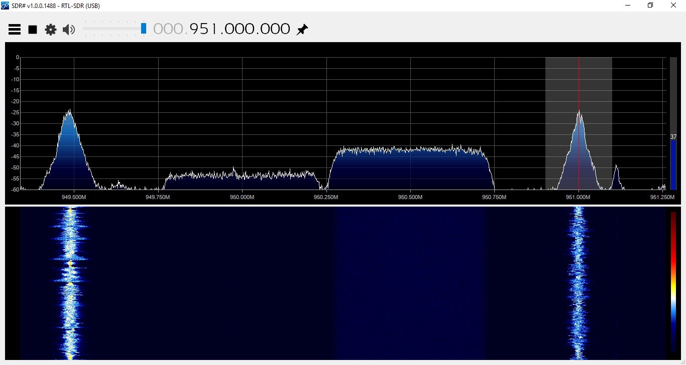
Using the scanner to look for open 950 MHz STL frequencies
Inexpensive portable FM receiver with RDS output for radio stations
Inexpensive Radio Direction Finder with a directional antenna
Inexpensive Satellite Aiming tool
Using SDR sharp and a NooElec NESDR Mini+ dongle, I made several scans of the 945-952 STL band in a few of our markets. Using the scanner and frequency search plugin, the SDR software very quickly identified all of the in-use frequencies. One can also look at the frequency span in the spectrum analyzer, but this takes a lot of processing power. The scanner plugin makes this easier and can be automated.
Analog and digital 950 MHz STL frequencies, Albany, NY
I also listened to the analog STLs in FM Wideband mode. Several stations are injecting their RDS data at the studio. There is one that appears to be -1500 Hz off frequency. I’ll let them know.
Next, I have found it beneficial just to keep the dongle and a small antenna in my laptop bag. Setting up a new RDS subcarrier; with the dongle and SDR# one can quickly and easily check for errors. Tracking down one of those nasty pirates; a laptop with a directional antenna will make quick work.
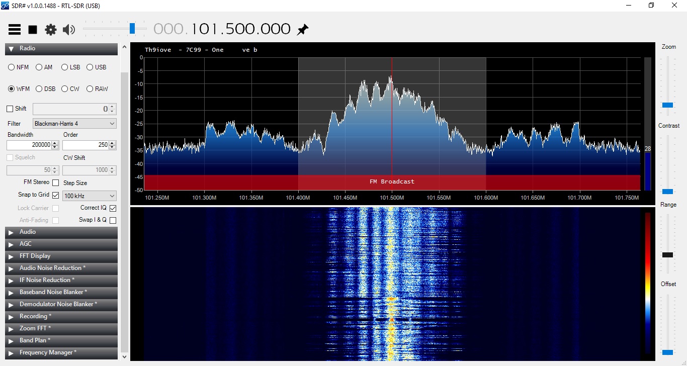
Something that I found interesting is the waterfall display for the PPM-encoded stations:
WPDH using RTL 2832U and SDR Sharp
Not only can you see the watermarking on the main channel, you can also see the HD Radio carriers +/- 200 KHz from the carrier frequency. That is pretty much twice the bandwidth allotment for an FM station.
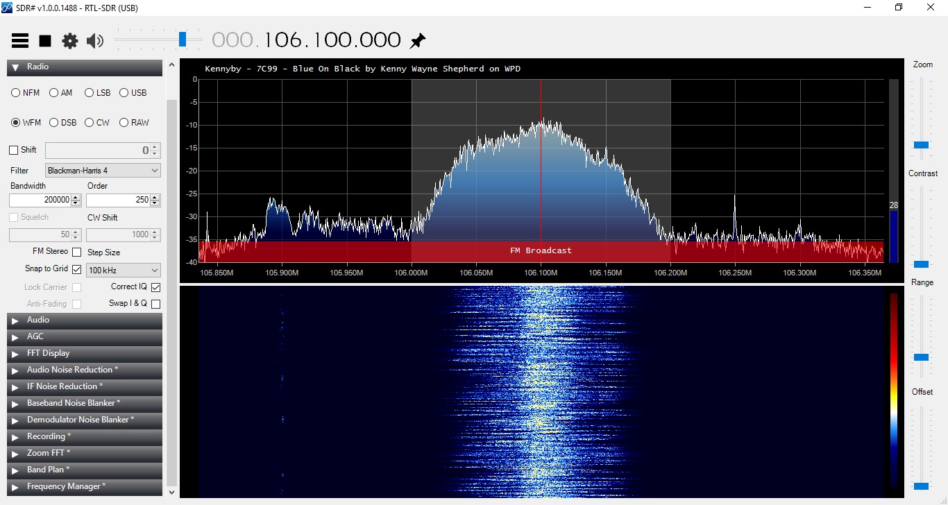
WDPA using RTL 2831U and SDR Sharp
Those two stations are simulcasting. WPDA is not using Nielson PPM nor HD Radio technology. There is all sorts of interesting information that can be gleaned from one of these units.
Aiming a satellite dish at AMC-8 can be a bit challenging. That part of the sky is pretty crowded, as it turns out. Dish pointer is a good general reference (www.dishpointer.com) and the Dish Align app for iOS works well. But for peaking a dish, the RTL 2832 dongle makes it easy to find the correct satellite and optimize the transponder polarization. Each satellite has Horizontal and Vertical beacons. These vary slightly in frequency, thus, but by tuning to the correct beacon frequency, you can be assured that you are on the right satellite. All of the radio network programming on AMC-8 is on vertically polarized transponders, therefore, the vertical beacons are of interest. Here are the vertical beacons for satellites in that part of the sky:
Satellite
Position
C band Vertical beacon (MHz)
L band (LNB) Vertical beacon (MHz)
Comment
AMC-8
139W
4199.5
949.25
AMC-7
137W
3700.5
1450.25
GOES15
135.4W
2209.086
N/A
NOAA WX
AMC-10
135W
4199.5
949.25
Galaxy 15
133W
4198
949.00
AMC-11
131W
4199.5
949.25
Galaxy 12
129W
3700.5
1450.25
For those in the continental United States, there is not much else past 139W, so AMC-8 will be the westernmost satellite your dish can see. Of course, this can be used in other parts of the world as well, with the correct information. Bringing a laptop or Windows tablet to the satellite dish might be easier than trying to drag a XDS satellite receiver out.
AMC8 vertical beacon output from LNB
In order to use the RTL-2832U, simply split the output of a powered LNB, and install a 20-30 dB pad in between the splitter and the dongle. Using the vertical beacon on 949.25 MHz, adjust for maximum signal.
For some other uses; look for the nearest and best NOAA Weather radio station. Several times the local NOAA weather station has been off the air for an extended period of time. Sometimes, another station can be found in the same forecast area. Heck, couple these things to a Raspberry Pi or Beaglebone black, and a really nifty EAS receiver is created for NOAA and broadcast FM. One that perhaps, can issue an alarm if the RSL drops below a certain threshold.
I am sure there are plenty of other uses that I am not thinking of right now…