The second post in the series, “things to do with a truck body tool box.”
We have this client who, several years ago, moved their translator to their AM tower. All is well for a few months, then the much beloved Harris SX2.5 transmitter begins burping. The SX2.5 transmitter was of an age when, apparently, VSWR fold-back circuits were just a gleam in Hilmer Swanson’s eye. The correct description of the sound made over the air during this event would be “motor boating,” because that is what it sounds like. Obviously, very undesirable.
Thus, the isocoupler was removed from the tower, dried out, waterproofed, and replaced. That lasted about six months.
Once again, the isocoupler was removed from the tower, a capacitor was remounted, drain holes and a small vent were added to the top of the unit and it was replaced. That lasted about a year.
I am getting a little tired of this and so is the client. Time to rethink the entire setup.
We had several leftover parts from various AM decommissioning over the last few years which included these nifty sample loop isolation coils:
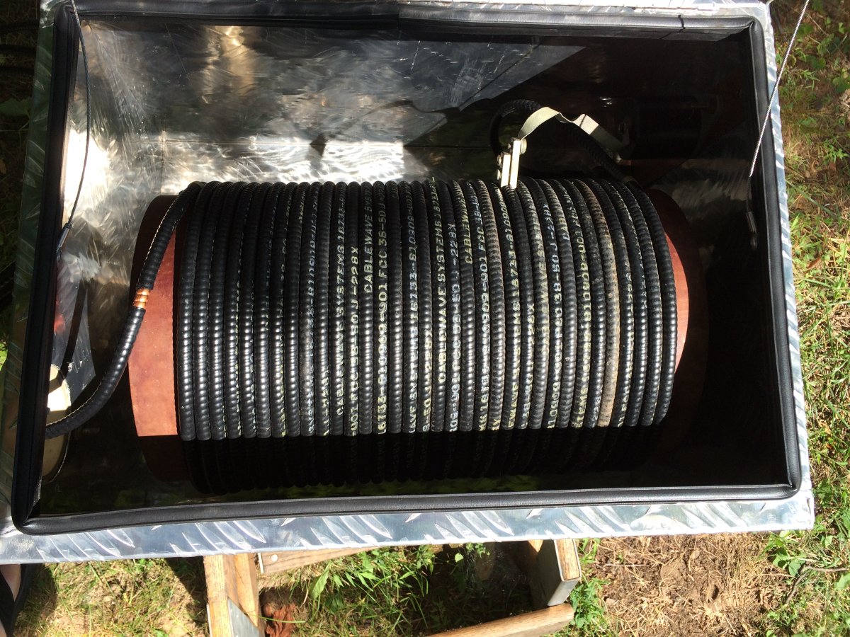
Why not repurpose one of these to make an isocoupler for the translator?
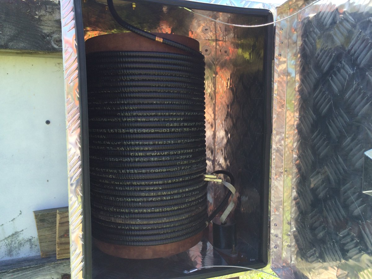
Enter; the truck body toolbox. This one is slightly smaller than the last one, measuring 23.5 x 18 x 16 inches (60 x 45 x 40.5 cm).
The isolation coil consists of 35 turns of 3/8 coax on an 11.5 inch diameter form. The coil length is 15 inches. I calculate the length of the coax on the coil to be out to be right around 100 feet using the π x D x (turns) formula. I measured the inductance with my analyzer, which came out to 200 μH. Not to shabby.

The coax is Cablewave FCC38-50J which has a velocity factor of .81 and the TDR shows it to be 100 feet also.
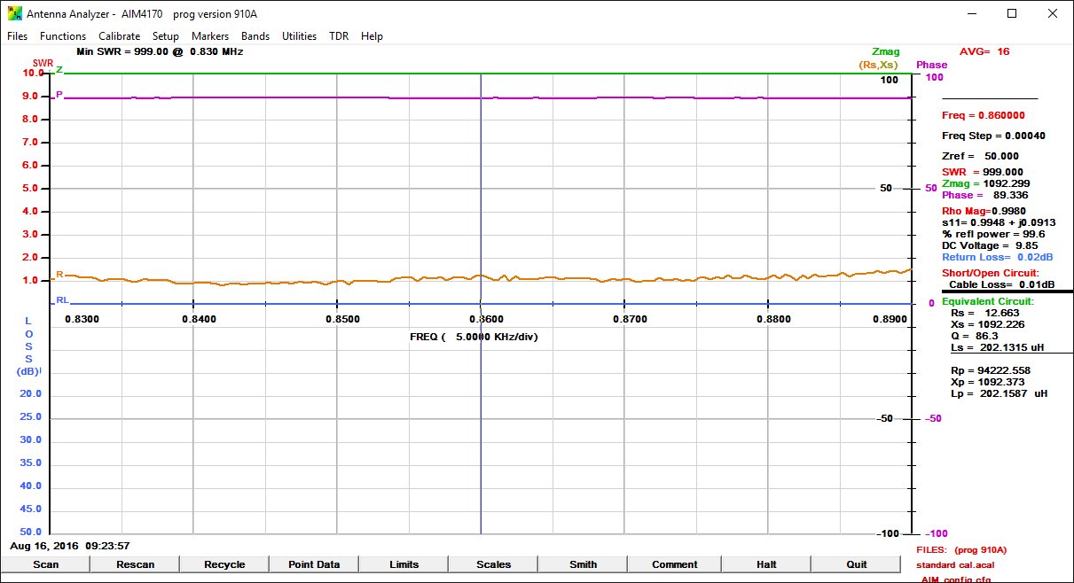
At 860 KHz, the isolation coil presents 1,200 impedance. I don’t think that will be good enough for that cranky old SX2.5. I decided to make a parallel LC circuit (AKA a tank circuit) to bring up the impedance.
Tank circuit formula:
Where:
FR = Resonance frequency in Hertz
L = Inductance in Henrys
C = Capacitance in Farads
Given that I have two leftover capacitors, one is a .001 μF and the other is a .0012 μF, those values determine where the coil needs to be tapped. I also wanted to have a good bit of coil in the circuit on the tower side before the capacitor tap to dampen any lightning strikes on the tower. Thus the inductance needs to be about 28 μH.
Using Wheeler’s coil inductance formula:
L= (d2 x n2)/(18d+40l)
where:
L = inductance in micro Henrys
d = coil diameter in inches
l = is the coil length in inches
n = is the number of turns
I removed a small portion of the outer jacket on the coil at approximately the 28 μH point (12 turns) then installed a .0012 μF capacitor. I used a small variable capacitor to tune for resonance on the carrier frequency. With this setup, at 860 KHz, there is >47,500 impedance. That goes down to about 16,000 ohms +/- 10 KHz.
That should make things better.
Then I mounted the coil and capacitor in the truck body toolbox. There is a fair amount of stray capacitance from the box itself, which raised the resonant frequency by 5 KHz.
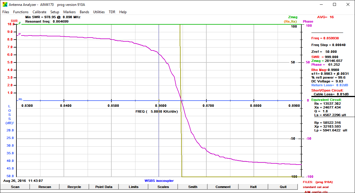
Resonance is slightly above the carrier frequency with the permanent fixed .0012 μF capacitor. I think this will change once the unit is connected to the station ground plane. The network analyzer indicated there is too much capacitance in the circuit. Unfortunately, this may be as good as it gets, however, the analyzer shows the impedances are still pretty high:
| Frequency (KHz) | Impedance (Ohms) | Deviation from Carrier (KHz) |
| 850 | 9,950 | – 10 |
| 855 | 14,720 | – 5 |
| 860 | 28,590 | 0 |
| 865 | 59,580 | + 5 |
| 870 | 24,780 | + 10 |
The base impedance of this tower is 34 ohms on the carrier frequency, so the isocoupler should be invisible to the transmitter across the 20 KHz occupied bandwidth of the station.
The FCC38-50J cable has a loss of 1.04 dB per 100 feet at 100 MHz, which is the figure I will use to calculate the insertion loss on the FM translator antenna system.
The old isocoupler is made with RG-214, but likely a somewhat shorter length. RG-214 cable has a loss of 1.9 dB per 100 feet at 100 MHz.
Installation:
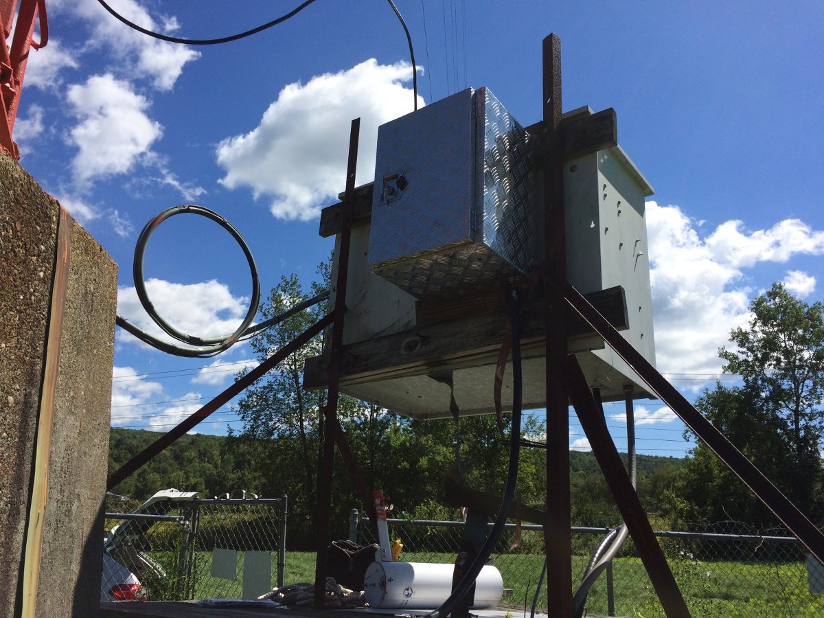
Before and after measurements with the network analyzer show a very slight change in the reactance at the tower base. Nothing major and easy enough to tune out with the series output inductor of the ATU.
If I were to do this again, I would simply tap the coil at ten turns from the bottom, measure the inductance and install the proper value capacitor. Since this had to be constructed with the parts on hand, less the truck body toolbox, it because a bit cumbersome to get close to the resonant frequency.
All this got me thinking; there are other possible uses for such a design. Crossing a base insulator with an Ethernet cable always presents some unique problems. I know the WISP forum that I read, they are always talking about how difficult it is to mount an antenna on an AM tower. What if… armored Cat5e or Cat6 cable was used with waterproof RJ-45 jacks? Something like that could carry Ethernet data and DC voltage past the base insulator to a three or four around sectorized access point and an edge switch or router mounted on the tower.

just thinking…
Anyway, it would not be hard to make coils and install capacitors for the right frequency


")


That SX is very cranky. As I understand it, several (And I mean many now) years ago, when the sister station about 25 miles away replaced their main rig with a Gates One, the plan was to replace this one as well. Not sure whatever happened to that.
Former in house staff (RIP) told me it would trip quite often. Especially, for whatever reason, in the winter time.
Eh, there is a reason for that. I was just looking at the ATU values and I don’t know why, but it was designed for a +3 degree phase shift. That made things a little wonky to say the least. Any time you get close to 0 degree phase shift one runs into the divide by zero problem. The component values were really screwy, creating a bandwidth problem and some pretty band asymmetry problems on the lower sideband that the transmitter does not like. I have the part on hand to make a nice +90 degree phase shift with normalish component values which should fix the issue once and for all.
That famous Harris engineer was Hilmer Swanson, no relation to Himmler!
Gak! Thanks Jim, I fixed it and threw in a link for those that don’t know.
Paul- very nice articles and explanations. Thanks for posting.
Although not specifically related to the AM portion of the discussion, FCC-38-50J coax had a problem with moisture contamination in the phase stabilization process at the factory. I first ran into this in Plymouth, MA and again in New Haven, CT. Measuring the length of the sample line on one of four towers using a TDR produced a measurement of 220 feet IIRC on a known physical length of 180 feet. Measuring a verified length of the same line on the ground produced a correct reading using the same TDR settings. Measuring with an ohmmeter found about 10k Ohms resistance inner conductor to shield. Slicing open the outer sheath showed a copper color on the foam with noticeable moisture. The two lines at the Ne Haven station exhibited the same symptoms and had to be replaced. A now deceased former employee of Cablewave admitted to me there was a problem at the factory during the manufacturing process.
When dealing with high impedance tank circuits one must be cautious of arcing especially under modulated conditions.