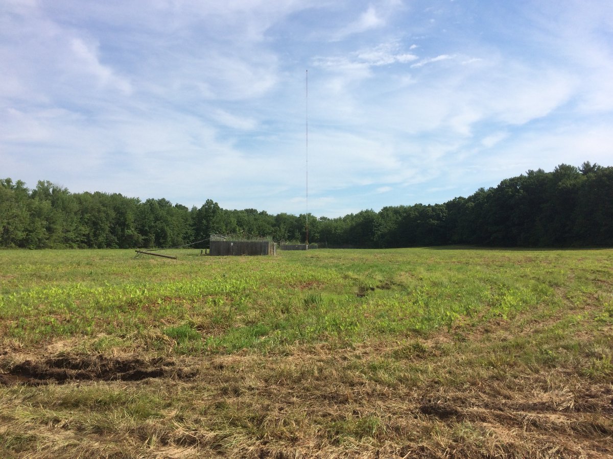
This is a topic I have covered before, but it is worth doing it again for future reference. The previous post covered downgrading an AM transmission facility for WGHQ, Kingston, NY.
This is part II of that process.
The old towers have been cut up and put in a scrap metal dumpster. They are off to China to be melted down and made into a submarine or a missile or a tank or something useful like that.
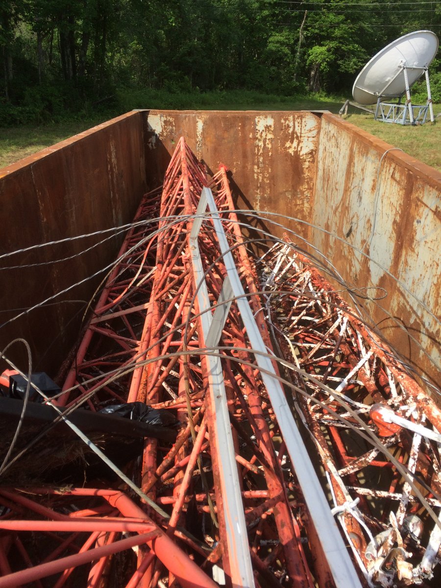
The directional array had three towers in a straight line with a common point impedance of 60 Ohms. Dropping two towers greatly changed the electrical characteristics of the remaining tower, therefore the existing ATU needed a bit of reworking to match the 50 Ohm transmitter output.
The first step, correct a few deficiencies left over from the old array.
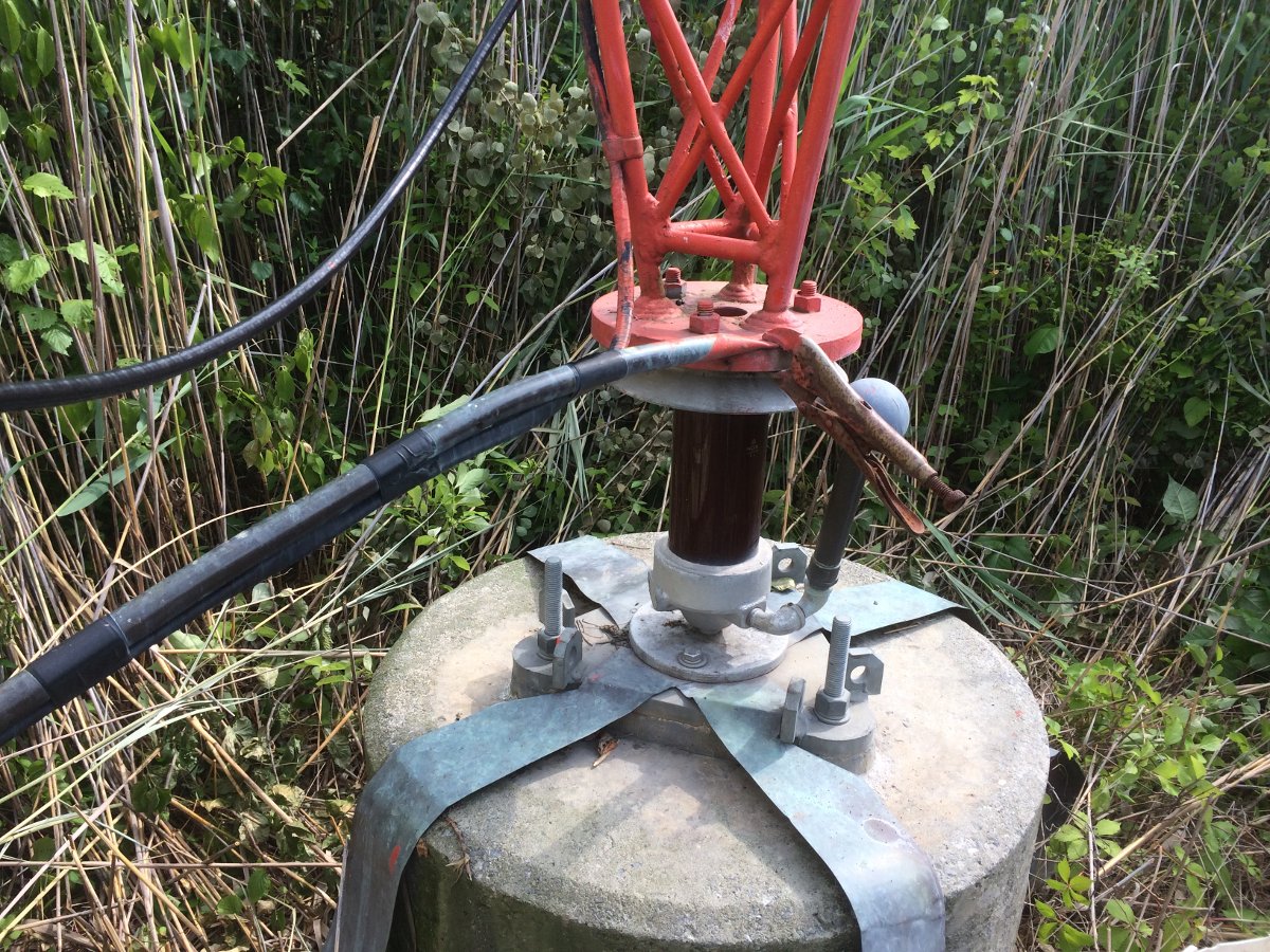
This vise-grip RF connection has to go. The problem is where the tower erectors attempted to solder the copper tubing. That tower base plate is pretty big and I would wager they didn’t use enough heat to make the solder connection. They were probably working in the winter time, thus the “temporary” fix. This tower was put up in 1993, so that temporary fix lasted 23 years.
I removed the offending tool and soldered the connection to another part of the tower with silver solder. The smaller crossbar made a good connection point.
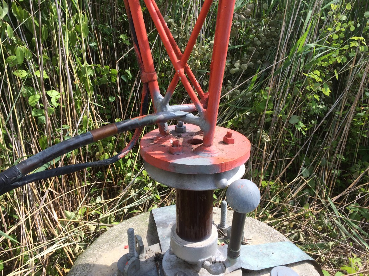
After soldering, I cleaned up and sprayed some grey primer on it to prevent rust from forming where I scraped the paint off.
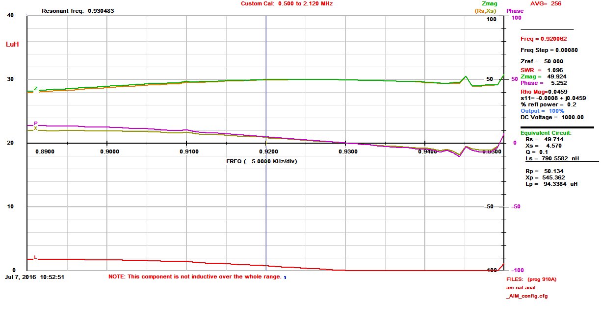
Next, I made an impedance measurement:
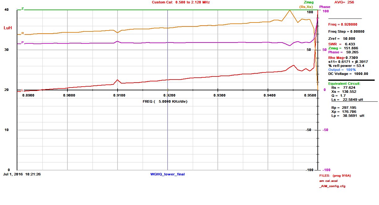
That junk on the upper part of the graph is coming from WHVW on 950 KHz. The tower itself looks pretty good, 77.6 Ohms resistance with 130 Ohms inductive reactance. Since this is not part of a directional antenna system, the ATU design is pretty straightforward. Given that WHVW on 950 KHz is located 10.41 miles away, a low-pass filter design is optimum. A basic low pass filter T network has inductive input and output legs with a capacitive shunt leg to ground.
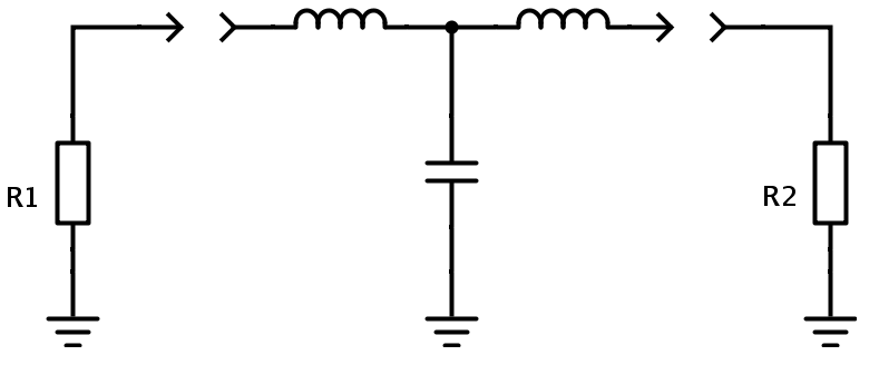
Each leg is used to match the 50 Ohm transmission line impedance (R1) to the 77.6 Ohm tower impedance (R2) and cancel out the 130 Ohms of inductive reactance. This is a vector impedance problem, much like a vector force problem in physics. Some basic arithmetic is required (always include the units):
X1, X2, X3 = √(Zin x Zout)
X1, X2, X3 = √(50Ω x 77.6Ω) or X = 62.28Ω
The value of inductance or capacitance for each leg is calculated using the basic inductance or capacitance formulas:
L (μH) = XL / 2πf(MHz)
And
C (μF) = 1 / 2πf(MHz) XC
Thus the input leg, or X1 = 62.28Ω / (6.28 x 0.92 MHz) or 10.78 μH
The Shunt leg, or X2 = 1 / (6.28 x 0.92 MHz x 62.28Ω) or .0028 μF
The output leg is a little different. The tower has 130 Ohms of inductive reactance that needs to be canceled out with a capacitor. Rather than cancel out all of the inductive reactance, then add an inductive output leg, the tower reactance can be used as part of the tuning circuit. The design calls for 62.28 Ohms inductive reactance, so 130Ω – 62.28Ω = 67.27Ω, which is the value needed to be canceled by a capacitor:
Output leg, or X3 = 1 / (6.28 x 0.92 MHz x 67.27Ω) or .0025 μF
A little Ohm’s law is used to calculate the base current for both the day and night time operations.

Thus the daytime base current is I = √(P/R) or I = √(1000 W/77.6Ω) or 3.58 Amps.
Night time base current is I = √(38 W/77.6Ω) or 0.70 Amps
Current handling requirements:
Base current is calculated to be 3.6 Amps at 1,000 Watts carrier power. Allowing for 125% peak positive modulation makes it 5.7 Amps. Having a safety factor of two or 11.4 Amps output leg and 14 Amps input leg.
Voltages: 353 maximum input voltage, 439 output.
Thus, 20 amp, 10 KV parts should work well.
The designed schematic for the ATU:
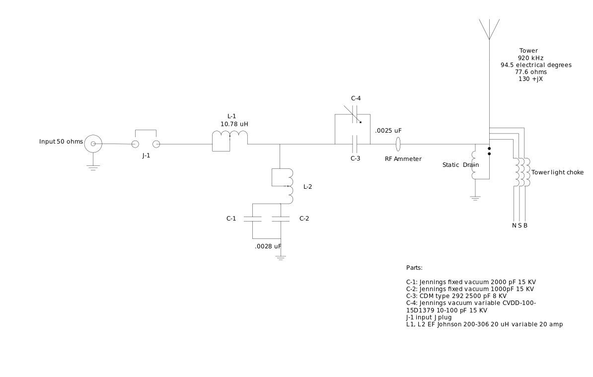
Putting it all together.
Since the tower looks fairly broad at 920 KHz, we are going to attempt a nice broadband ATU to match it. This station is currently programmed with a classic country format, and I have to tell you; those old Conway Twitty, Merle Haggard, Patsy Cline, et al., songs sound pretty good on the old AM radio. The Subaru stock radio has HD, which also has a nice broad IF section, thus allowing all those lovely mid-high-range frequencies through.
This is the existing ATU, which I believe was built by Collins in 1960:
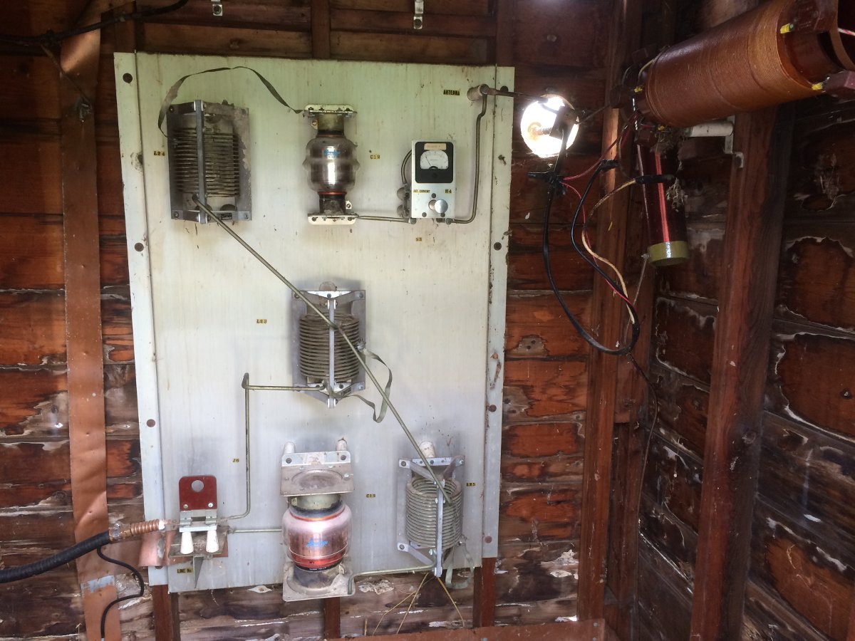
The ATU building is a little rough, but the ATU itself is in remarkable shape for being 56 years old. The input leg inductor is in the center and will be reused as is. The large Jennings vacuum capacitor at the bottom is a part of the shut leg. Its value is 2000 pF at 15 KV. The top vacuum capacitor is a series output cap, its value is 1000 pF at 15 KV. The basic plan is to move the upper cap down in parallel with the bottom cap. The shut leg inductor will be kept in place to tune out any access capacity. For the output leg, I have a 2500 pF mica cap and a 10-100 pF variable cap connected in parallel. The inductor on the output leg will be removed.
After some re-work on the ATU components, I tuned everything up. The easiest way to do this is to disconnect the legs, measure them individually, and adjust them for the desired reactance, which in this case is 62.28 ohms or thereabouts. The output leg was measured with the tower connected since the tower reactance is a part of the tuning circuit. The input leg was right about 10 μH. The shunt leg turned out to be about 0.002 μF. This is often the case, theoretical values are slightly different than field values due to stray capacitance and inductance in the connecting straps, etc.
This is the load, as measured at the output terminals on the transmitter:
Slightly asymmetric on 910 KHz, but overall pretty good. There is a fair amount of phase rotation in the transmission line due to the length from transmitter to the tower (855 feet, 260.6 meter), which works out to be 0.93 wavelength allowing for the 86% velocity factor of the transmission line.
Time to pack up and go home.


The spherical object on the short ‘stalk’ at the tower base, is that a spark-gap for lightning protection?
Thank you so much for all the detail! It definitely helps me get a handle on the types of issues and situations I’ll run into once I get into the awesome world of broadcast engineering!
That isn’t the only vice-grips out there doing RF duty. I think you’re right, they can’t get that base plate hot enough and the connection soon fails. I’ve flattened and drilled out the end of the RF feeder and torqued it down under a tower bolt, but your fix is better.
Geoff, yes that is the ball gap which lightning jumps when the tower is struck. The proper procedure for setting the distance between the two balls is to modulate the transmitter heavily then adjust the distance until it starts to arc, then back off a little bit.
Chris, that why I did it.
Chuck, I know of a few ground straps being held together by vise grips as well
Paul –
Very interesting piece.
Can you show the formulas for base current at 125% modulation and also how the input and output voltages were calculated?
I get different values but am not that confident my formulas are correct..
Very nice. Thanks for all of the detail.
Another great use for vice-grips. I make sure there is money in the budget for a supply of them!.
Paul
What software were you using to show the antenna tuning?
How are the ground radials for the remaining tower?
Were the radials for the removed towers tied to the ground for the remaining tower or will they be doing nothing left to rot?
Is there some reason they could not reuse the old towers? I suppose they are old and rusty, but if the one being used is still good, why not the others? Paint them up and sell them for another station’s upgrade. I’d keep them around in case the main tower fails or falls.
Vice grips aren’t to bad, probably make pretty good contact, though it is quite funny to see that. You ain’t soldering that in the winter, not only that, you could bust the insulators with the cold to hot change using a torch. A more permanent fix would be to use a C clamp or something of that nature, but you did whatever works. Ideally a giant crimp on ring attached to one of the bolts would work, but that’s a piece that you would have to order.
Funniest thing I have seen in radio is a control board connected to a phone punch down panel….with the station’s main left and right audio feeds connected by 3 gator clips each channel. I saw that and I was like, what happens if someone’s shirt catches it? It worked. Never as bad as the CD player with RCA phono plugs, with an RCA cord cut off and duct-taped to a two conductor sheilded wire connected to the contol board. As if an RCA jack had enough power to drive an input transforer. Needless to say, that was the crappiest sound you could possibly have on air, even a Radio Shack matching transformer would have sounded better. We couldn’t believe that that is how they ran it. I’d seen pirate stations that have better rigs than that. It was just entertaining, as I was working for the new competition that would soon sign on.
Anyway, while we all like to engineer stuff well, there always seems to be a few of those “disney mouse character” things in a Radio Station.
Won’t the old ground radials cause a distortion in the direction of the signal? You would get at least a light oval distortion as the two ends will radiate farther due to better grounding.
The condition of that rig is amazing considering the environment!
Neil;
The cost to have the tower dismantled so it can be re-used probably exceeds the value of the tower. It’s often less costly to drop them and scrap the steel.
Here in WI it’s unlikely such a tower could be re-used unless complete engineering data was available from the manufacturer and the stars have all aligned in your favor.
In absence of a welded connection tab or handy bolt, I’ve flattened the end of the RF feeder and used a pair of hose clamps (erm.. make that ‘Round Member Adapters’) to clamp it to the tower leg. After scraping the paint off of course. Not permanent, but better than sacrificing a perfectly good vice grips.
Resourceful, on-the-spot engineering—nicely done!
The formulas you used provide not only the desired impedance match, but also a 90-degree phase lag between the input and the output resistance (radiation resistance). Any particular reason for this approach other than the simplicity of the computations? The network has low Q, so it enables broad band operation, but the same network with and even smaller phase lag (e.g. 60 degrees) may provide greater bandwidth. The formulas are more complicated, however. So is the 90-degree network is more than adequate for the task, with other solutions regarded as not being worth the trouble?
Incidentally, I don’t work in the broadcast industry, but stumbled upon this web site about a year ago. I’ve got it bookmarked and check in every now and again.
Rod, I multiplied the carrier power by five, calculated the current then added a very generous safety margin.
Scott, the software is AIM, which comes with the AIM 4170
Dave, You are correct, 90 degree phase shift is just to simplify the math. Since this is a series excited tower, it is fairly broad by nature. A skirted tower is a different animal, especially if greater than 120 degrees or so. In those cases, a fair amount of phase rotation might be needed to keep the side bands symmetrical about the carrier frequency.